Char-Broil 10101480 User Manual
Page 14
3
Qty: 3
#10x3/8"
Self-Tap Screw
Make sure valve
is centered with burner tube
Burner Tube
Valve end
Valve and Burner
Centered
B
A
Electrode
Spade end
of ignitor wire
D
View is shown
with unit upside-down
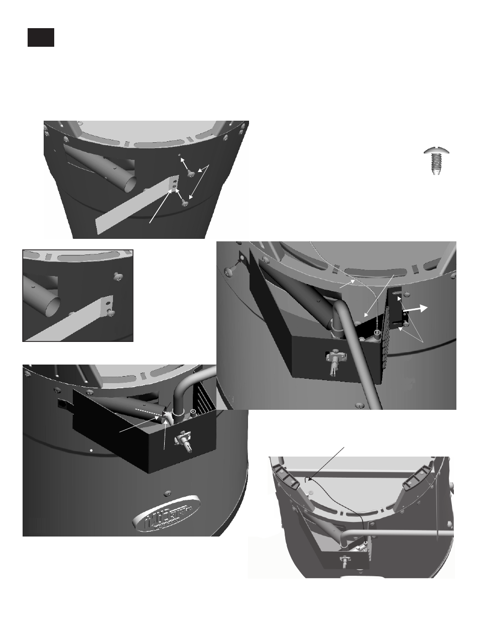
Assemble the control panel to the appliance:
Install 1 each #10x3/8” self-tap screw into the bottom hole of the Heat Shield shown below (A). Install a second
#10x3/8" self-tap screw into the top hole of the appliance body shown below (A). Do not completely install the
screws at this time. Be sure two threads are engaged into the appliance body. (A1)
Slide the control panel slots under the screws heads while holding the heat shield in position between
control panel. Secure with 1 each #10x3/8" self-tap screw as shown below (B).
•
•
appliance
body and louver side of
•
With control panel installed, review ( C) to ensure correct assembly.
•
Attach spade end of wire to electrode (D).
14
Heat Shield slides
between Control Panel
and body and underneath
Ignitor Wire.
Heat shield
in place
Control Panel
Slots
Bottom hole of heat shield
View is shown
with unit upside-down
A1
#10x3/8"
Self-Tap Screws
loosely installed.
#10x3/8"
Self-Tap Screw
Ignitor
wire
C
#10x3/8"
Self-Tap Screws