Cps725sl – CyberPower Systems CPS725SL User Manual
Page 3
CPS725SL
Guaranteed Uninterruptible Power System
1
IMPORTANT SAFETY INSTRUCTIONS (SAVE THESE INSTRUCTIONS)
This manual contains important safety instructions.
Please read and follow all instructions carefully during
installation and operation of unit. Read this manual
thoroughly before attempting to unpack, install, or oper-
ate.
CAUTION!
To prevent the risk of fire or electric shock,
install in a temperature and humidity controlled indoor
area, free of conductive contaminants. (Please see
specifications for acceptable temperature and humidity
range).
CAUTION!
To reduce the risk of electric shock, do not
remove the cover except to service the battery. No user
serviceable parts inside except for battery.
CAUTION!
Hazardous live parts inside can be energized
by the battery even when the AC input power is discon-
nected.
CAUTION!
UPS must be connected to an AC power
outlet with fuse or circuit breaker protection. Do not plug
into an outlet that is not grounded. If you need to de-
energize this equipment, turn off and unplug the unit.
CAUTION!
To avoid electrical shock, turn off the unit and
unplug it from the AC power source before servicing the
battery or installing a computer component.
DO NOT USE FOR MEDICAL OR LIFE SUPPORT
EQUIPMENT!
CyberPower Systems does not sell prod-
ucts for life support or medical applications. DO NOT use
in any circumstance that would affect operation or safety
of any life support equipment or with any medical applica-
tions or patient care.
DO NOT USE WITH OR NEAR AQUARIUMS!
To re-
duce the risk of fire or electric shock, do not use with or
near an aquarium. Condensation from the aquarium can
cause the unit to short out.
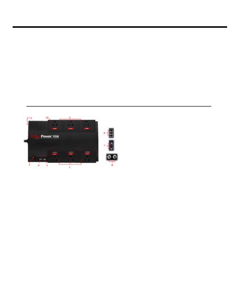
DESCRIPTION
1.Battery/Surge Outlets
Provides three battery powered/surge outlets for con-
nected equipment and insures temporary uninterrupted
operation of your equipment during a power failure.
2.Full-Time Surge Protection Outlets
Provides three always on surge suppression outlets.
3.Power Switch
Can be used as a mater on/off switch for equipment
connected to the battery power supplied outlets.
4.Power On Indicator
This LED is illuminated when the utility condition is normal
and the UPS outlets are providing power, free of surges
and spikes.
5.Electrical Wiring Fault Indicator
This LED indicator will illuminate to warn the user that a
wiring problem exists, such as bad ground, miss ground
or reversed wiring. If this is illuminated, user is advised to
disconnect all electrical equipment from the outlet and
have an electrician check to ensure the outlet is properly
wired.
6.Circuit Breaker
Located on the side of the UPS, the circuit breaker serves
to provide overload and fault protection. Under normal
operating conditions, the circuit breaker is depressed.
7.Serial Port to PC
This port allows connection and communication from the
DB-9 serial port on the computer to the UPS unit. The
UPS communicates its status to the PowerPanel™ soft-
ware. This interface is also compatible with the UPS
service provided by Windows NT and Windows 2000.
8.Coaxial Cable Surge Protection
Connect the coaxial cable from your cable / antenna dish
source to one of the surge protector’s video connectors
market “IN”. With another section of coaxial cable, con-
nect the surge protector’s corresponding video connector
marked
9.Communication Protection Ports
Communication protection ports will protect any standard
modem, fax or telephone line.
10.Outlets Designed for AC Adapters
Allows six AC power adapter blocks to be plugged into the
UPS without blocking adjacent outlets.
INSPECTION
The box should contain the following:
(1) PowerPanel™ software (floppy disk); (1) serial interface cable (DB-9);
(1) telephone communication cable; (1) user manual; (1) warranty registration card;
(1) USB adapter ; (1) UPS unit.