Crestron cnx-pvid8x4 video distribution switcher, Specifications – Crestron electronic CNX-PVID8x4 User Manual
Page 2
Crestron Electronics, Inc. 15 Volvo Drive
l
Rockleigh, NJ 07647
Tel: 800.237.2041 / 201.767.3400
l
Fax: 201.767.1903
www.crestron.com
Specifications subject to change without notice. Doc.6033B 08/07
All brand names, product names and trademarks are the property of their respective owners.
©2007 Crestron Electronics, Inc.
AVAILABLE ACCESSORIES
CNX-PBVR4
CAT5 Balanced Video Receiver
CNXRMC
Room Solution Box
CNXRMCLV
Enhanced Room Solution Box
C2N-DAP8RC
7.1 Surround Sound Processor and Room
Solution Box
SPECIFICATIONS
Video & Digital Audio
Signal Types: Component (YP
B
P
R
), S-Video (Y/C), or composite video; digital audio
Video/HDTV Formats: 480i (NTSC), 576i (PAL), 480p, 576p, 720p, 1080i
Digital Audio Format: S/PDIF coaxial
Bandwidth: 100MHz (unbalanced)
Crosstalk: -60dB
Connectors
INPUT 1 – 16: (128) RCA female comprising (3) levels of (16) video inputs, and (1) level
of (16) digital audio inputs, each with parallel loop-thru;
Configurable as:
- 16 inputs – any type: component, S-Video, or composite video + 16 digital audio
- 24 inputs – 8 composite, 8 S-Video/composite, 8 component/S-Video/composite, &
16 digital audio
- 32 inputs – 16 composite, 16 S-Video/composite, & 16 digital audio
Input Level: 1 V
P-P
nominal
Signal Sensing Threshold: 0.25 V
P-P
Connect to video/digital audio outputs of source devices or CNX-PBVR4, with loop-thru to
additional CNX-PVID8X4** or terminator (75 ohm terminators included)
OUTPUT 1 – 8 (RCA): (32) RCA female comprising (3) levels of (8) video outputs, and
(1) level of (8) digital audio outputs;
Output Level: 1 V
P-P
nominal
Output Impedance: 75 ohms
Each output functionally paralleled with corresponding wire pair of respective CAT5
output
OUTPUT 1 – 8 (CAT5): (8) 8-pin RJ45 female, shielded, CAT5 balanced video output ports
Output Impedance: 100 ohms per pair
Connect to room solution boxes, touchpanels, or any “CH” CAT5 audio ports*
NET: (1) 4-pin 5mm detachable terminal block
Cresnet slave port, connects to Cresnet control network
G: 6-32 screw, chassis ground lug
Buttons & LED Indicators
PWR: (1) green LED, indicates 24 Volts DC power supplied from Cresnet control network
NET: (1) yellow LED, indicates communication with Cresnet system
OUTPUT 1 – 8: (8) red LED’s, indicate if outputs are assigned an input
ACTIVE VIDEO INPUT 1 – 16: (16) red LED’s, indicate presence of a video signal at a
given input
SELECT 1 – 4: (1) miniature pushbutton and (4) red LED’s, select which level’s status is
currently displayed
SETUP (rear): (1) red LED, used for touch-settable ID (TSID)
Power Requirements
Cresnet Power Usage: 40 Watts (1.67 Amps @ 24 Volts DC)
Environmental
Temperature: 41° to 104°F (5° to 40°C)
Humidity: 10% to 90% RH (non-condensing)
Enclosure
Black metal, 4U 19-inch rack-mountable (rack ears included)
Dimensions
Height: 7.06 in (17.93 cm), 6.97 in (17.70 cm) without feet
Width: 17.28 in (43.89 cm), 19.0 in (48.26 cm) with rack ears
Depth: 8.67 in (22.02 cm)
Weight
9.81 lbs (4.45 kg)
*
Maximum CAT5 Distance: 500 feet for component, 750 feet for composite and S-Video
**Room outputs are expandable by cascading the inputs of multiple units using standard
RCA interconnect cables. Crestron recommends cascading no more than four (4) units.
However, the actual number of possible units in a system is virtually unlimited, although
additional equipment may be necessary to maintain signal integrity. Contact Crestron for
additional assistance.
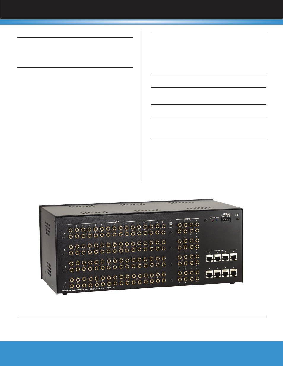
Crestron CNX-PVID8X4 Video Distribution Switcher
Rear View