Block diagram, Specifications, Antenna system crestron srd-ant-4-pak – Crestron electronic Antenna System SRD-ANT-4-PAK User Manual
Page 6
Antenna System
Crestron SRD-ANT-4-PAK
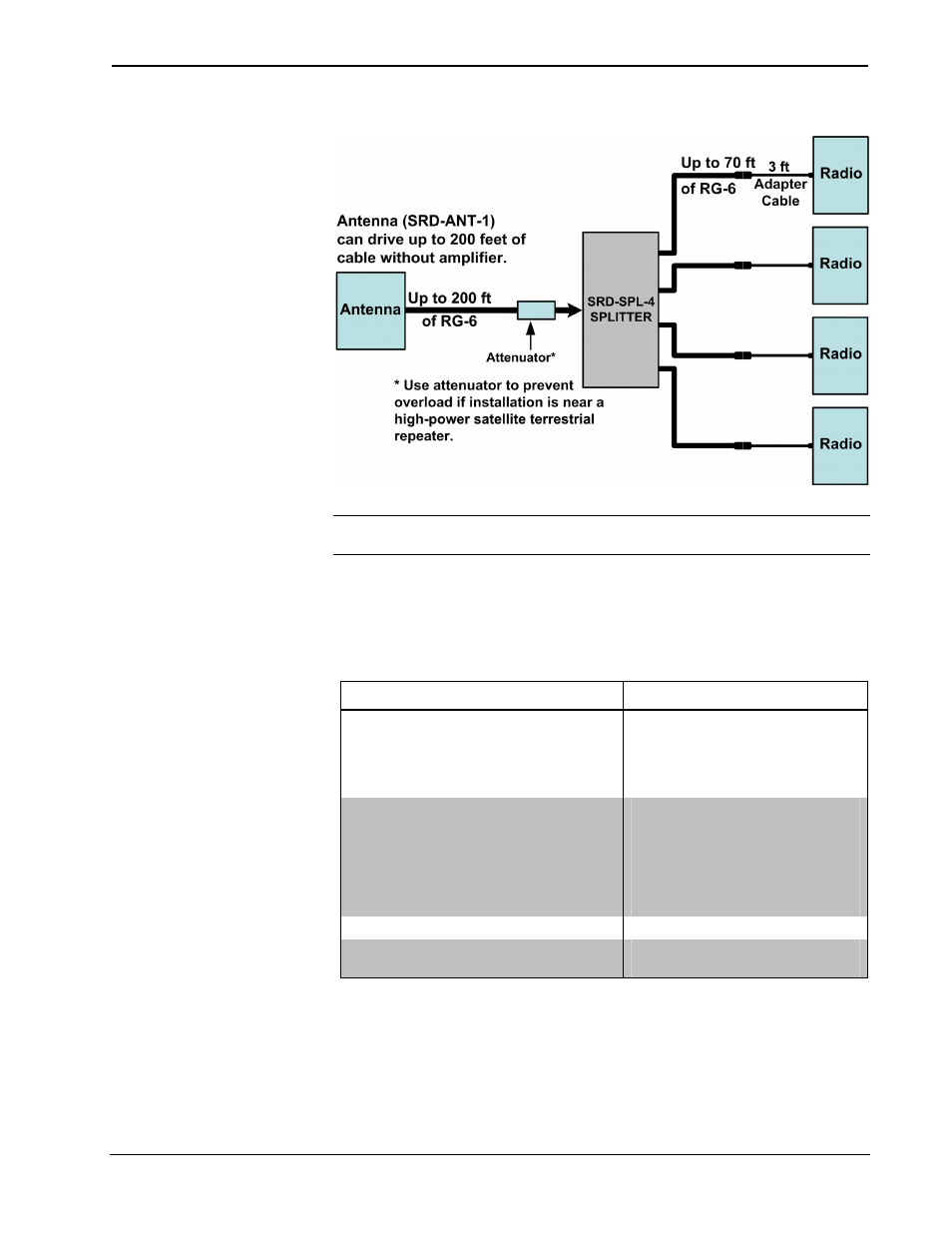
Block Diagram
NOTE: In this typical layout example, the sum total of all the cable segments
between the antenna output and the most distant radio should not exceed 275 feet.
Specifications
Following are specifications for the SRD-ANT-4-PAK.
SRD-ANT-4-PAK Specifications
SPECIFICATION DETAILS
Antenna
Gain
Polarization
Output
connector
Wind
resistance
12dBi (Typical)
Left hand circular
F-female
Up to 100 MPH
Splitter
Gain at 2.335 GHz
Max noise figure
Max input signal
Current
consumption
DC power passing
DC voltage drop (output to input)
8 dB min
3 dB
-10 dBm
1
40 – 100 milliamps
all ports (diode protected)
0.5 VDC typical
Environmental Temperature
-40° to 150°F (-40° to 66°C)
Humidity
0% to 98% RH
(non-condensing)
(Continued on following page)
2
• Antenna System: SRD-ANT-4-PAK
Installation Guide – DOC. 6723A