Rear panel connections and controls – Crowson Technology A300 User Manual
Page 5
IR Input Jack: Power on, off and volume can be controlled through the IR Input Jack when the front panel of the
A300 is hidden. Connect a mono 1/8” control cable (signal on tip) from your remote control system to the IR Input Jack.
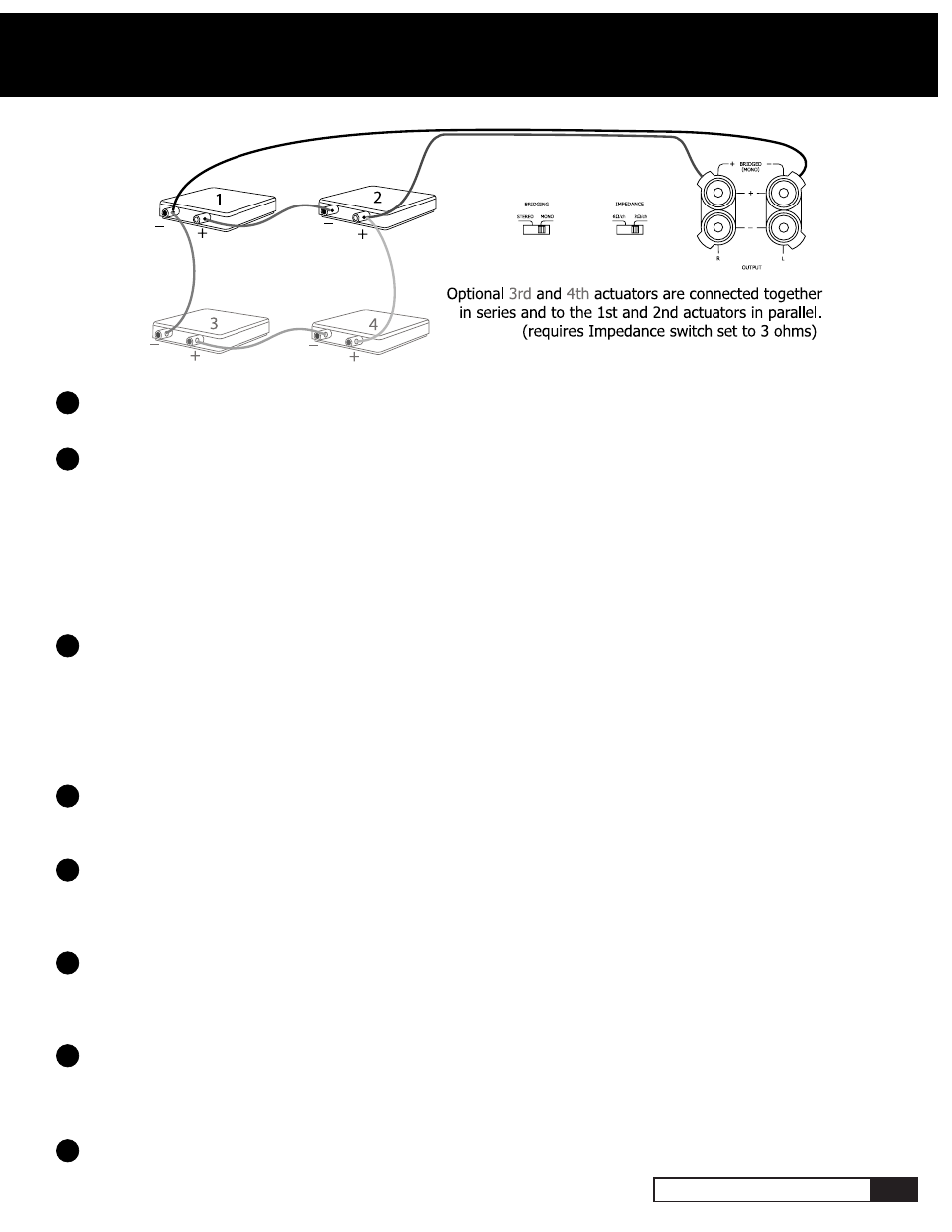
Bridging Switch: A single speaker cable can be used to power one to four TES-100 actuators in a Mono
Configuration by selecting the “Mono” position of the Bridging Switch. Two or four TES-100 Actuators can be powered in
mono by using the two red Output Binding Posts (bridged) and wiring the transducers in a series configuration as shown
in the Mono Configuration illustration. One TES-100 Actuator can be powered in mono by connecting the actuator’s red
and black binding posts directly to the two red Output Binding Posts (bridged). When using the Mono Configuration, L, R
and LFE inputs should still be used, the rear Impedance Switch should be set to 3Ω/ch and the minimum impedance load
should be 6 ohms.
FOR NORMAL OPERATION WITH STEREO MOTION THE BRIDGING SWITCH SHOULD BE SET TO “STEREO”.
THE A300 POWER CORD SHOULD ALWAYS BE REMOVED BEFORE MOVING THE BRIDGING SWITCH.
Rear Power Switch: When the Rear Power Switch is set to the “Auto” position, the A300 will be turned on when
an audio signal is present at its L, R or LFE Input jacks. After the audio signals cease, the A300 will remain on for
approximately five minutes. This prevents unintended turn-off during pauses in your music or movies. The “Auto” position
also changes the front panel Power button to a standby on and off selector. The red Power Standby Indicator on the front
panel above the Power Button indicates a standby condition. When the Rear Power Switch is in the “Manual” position, the
auto turn-on function is disabled and the A300 must be turned on and off manually with the Power Button on its front
panel or remote control.
Impedance Switch: For a single pair of TES-100 Actuators (6 ohms each) the Impedance Switch should be set
to the 6Ω/ch position. The Impedance Switch must be set to the 3Ω/ch position when using more than two TES 100
Actuators. Do not use more than four total TES 100 Actuators.
Ground Switch: The Ground Switch disconnects or “lifts” the audio circuit ground from the chassis ground. This
often helps to eliminate audible hum that results from ground loops. Begin with the Ground Switch in the “Earth” position.
If you feel or hear background hum in the Actuators connected to the A300, try setting the Ground Lift Switch to the
“Lift” position.
Voltage Selector Switch (115v - 230v AC): The 115V position of this switch is correct for North America; most
other regions require setting it to 230V. Make sure the 115/230V switch is set for the correct AC line (mains) voltage
before you connect the A300’s power cord and TES-100 Actuators. THE A300 MAY BE SERIOUSLY DAMAGED IF THIS
SWITCH IS SET INCORRECTLY.
Fuse: Check to make sure the proper Fuse is used for your AC line (mains) voltage. Use a small flathead screwdriver
to pry open the Fuse holder. For 230V use a T3.15AL250V fuse. For 115V use a T5AL250V Fuse. The Fuse is a “Slo-Blo”
type, sized at 5mm diameter x 20mm. The Fuse will not blow unless the unit is overstressed. BEFORE REPLACING THE
FUSE, CORRECT THE CONDITION THAT CAUSED IT TO BLOW IN THE FIRST PLACE.
Power Cord Socket: Plug the AC Power Cord into the Power Cord Socket.
A300 OWNER’S GUIDE
5
Rear Panel Connections and Controls
Mono Configuration
10
11
12
13
14
15
16
17