Efi controls, See figure 10.10, M48 tank – Cub Cadet M48 User Manual
Page 30
M48 Tank
26
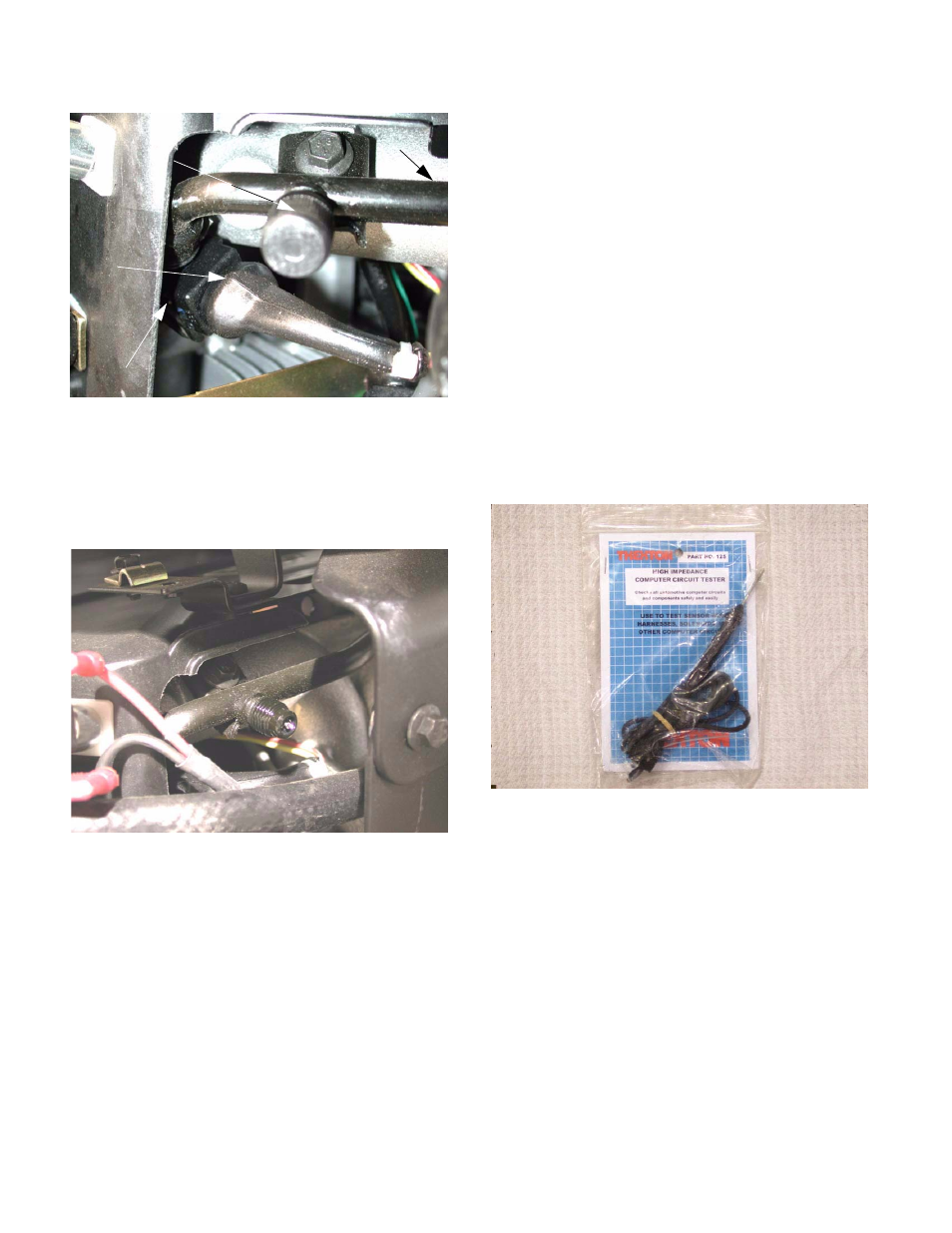
10.11. The shrader valve can be used for checking fuel
pressure. Fuel pressure readings obtained at
the shrader valve can help pin-down problems
with the fuel pump or the fuel pressure regulator.
See Figure 10.11.
10.12.Before any service is performed on the pressur-
ized portion of the fuel system, the engine must
be allowed to cool, and the pressure should be
relieved.
10.13.To relieve pressure from the fuel system:
•
Turn the key switch off.
•
Remove the 10A in-line fuse that protects the
fuel pump.
•
Start the engine normally. It will run for only a
few seconds.
•
Turn the key switch off.
11.
EFI CONTROLS
The Fuel injection system used by Kohler is an
adapted version of the Bosch Motronic automotive sys-
tem.
NOTE: Do not connect or disconnect any electri-
cal components with the key switch in the “on”
position. The resulting arc could cause immedi-
ate and sever damage to the ECU.
NOTE: If using a circuit tester, use only a high
impedance tester (eg. Thexton model 125).
Conventional testers pass the current they are
checking through a small incandescent bulb. In
some cases, the bulb draws more power than
the circuit in the computer, over-loading the cir-
cuit and complicating the diagnostic process by
inducing a circuit failure. High impedance
testers do not actually pass much current, and
the LED indicator will not draw enough power to
damage the circuitry. See Figure 11.0.
11.1. The EFI engine has a throttle valve or “air valve”
similar to that of a carburetor. There is no fuel
mixed into the air at this point. The throttle valve
only regulates the amount of air that enters the
engine.
11.2. The throttle responds to the governor just like it
would with a carburetor.
11.3. The computer (ECU) takes in information from
various sensors, and decides how much fuel the
engine should have to maintain a correct fuel/air
mixture. The ECU then sends electrical pulses
to the individual injectors, triggering them to
spray fuel into the intake tract.
Figure 10.10
Fuel injector
Fuel
rail
electrical
connectio
n
for injecto
r
Cap for
shrade
r
valve
Figure 10.11
Figure 11.0