Skyrouter connections – CTEK Z1204 Relay Module User Manual
Page 8
TN0019 – Z1216 I/O and Z1204 Relay Module
Hardware Configuration
TN0019 - 28 March, 2011
8
SkyRouter Connections
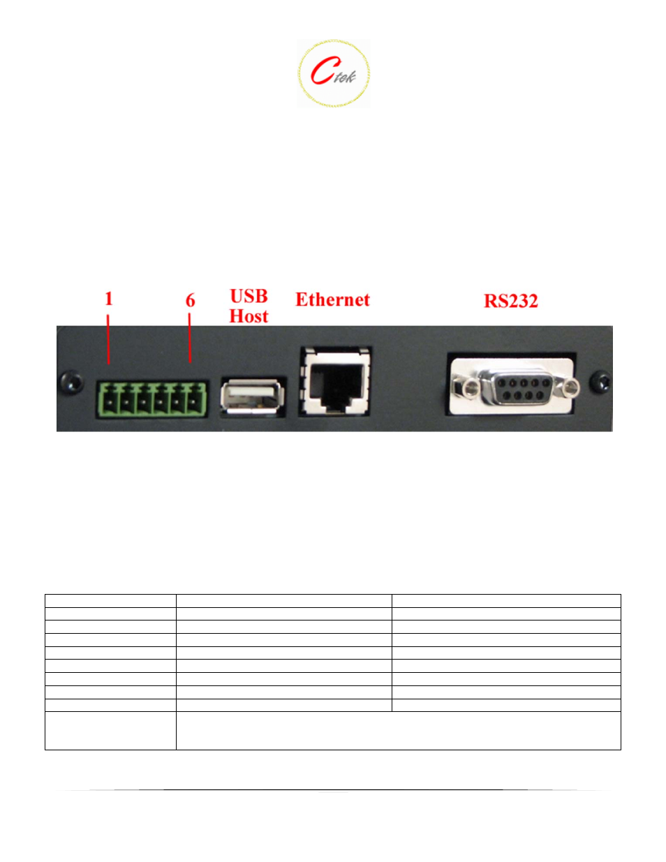
Figure 8 shows the connections available on a Z Series SkyRouter that can be used to interconnect with
I/O modules.
Figure 8 - Z4200U/Z4300U/Z4400U Connections
Connector J1 (green connector) supports four separate functions, power, relay contact closure detection,
relay driver output, and the RS-485 serial port. Contact closure pins 2 and 4 are shared with the RS485
serial port. To option remove the circuit board and locate the 3-pin headers JP1 & JP2 behind the green
connector. Facing the end of the board containing the green connector JP1 and JP2 should have jumpers
center to right to use the discrete I/O (Din, Dout), and JP1 and JP2 should have jumpers center to left to
use the RS-485 serial port. Auxiliary serial port parameters (baud, parity, etc.) are set using the
RS232/485 configuration screen. From the factory the unit ships with the auxiliary RS-485 serial port
enabled and configured as a master device. The J1 pin out configuration is as follows:
Terminal Block Pin
JP1 & JP2 (internal) Center to Right
JP1 & JP2 (internal) Center to Left
Pin 1
Din Src – Discrete Input Source
Pin 2
Din – Discrete Input (See Appendix A)
TR- of RS-485 serial port
1
Pin 3
Dout Gnd – Discrete Output Ground
Ground of RS-485 serial port
2
Pin 4
Dout - Discrete Output
3
TR+ of RS-485 serial port
1
Pin 5
Power supply Ground
Power supply Ground
Pin 6
Power supply +12VDC
Power supply +12VDC
Note 1
Note 2
Note 3
Connect a 120 ohm resistor across pins 2 --> 4 for multi-drop configurations
Available as a third wire ground for use in noisy environments
Discrete output is rated at 200ma @ 24 volts maximum sink current