Cooper Instruments & Systems DCM 465 Voltage Bridge Amplifier User Manual
Page 3
CF 29
3
4/2001
maximum of 1,000 by means of an external resistor connected across terminals 12 and 13. The size of the external
resistor can be calculated using the gain formula in the specifications. When doing this, the coarse gain potentiometer
should be turned fully clockwise. The fine gain pot can then be used for final gain adjustment. The output offset adjustment
range is ±0.5V.
The amplifier can withstand input voltages up to 15 Volts without damage. The output of the amplifier is filtered to be 3 dB
down at 3 Hz using a double pole Butterworth response filter to minimize the effects of high frequency electrical and
physical noise on the system. The output of the amplifier is ±10 Volts at 5mA making it compatible with modern data
acquisition techniques and systems.
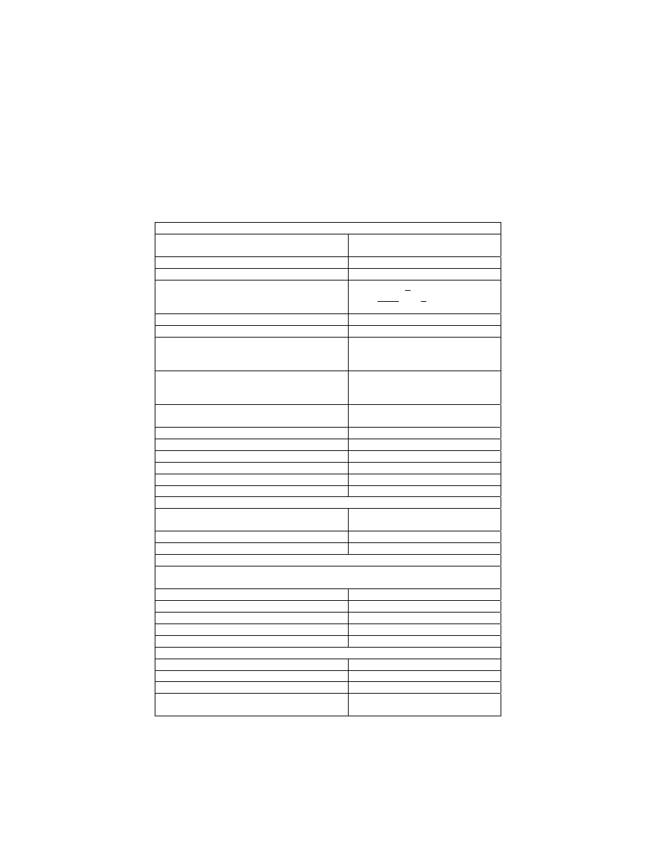
Specifications
(Typical @ 25°C unless noted)
Amplifier
Gain Range
With external R
40-250
to 1,000
Gain Temperature Coefficient
200 ppm/°C
Gain Potentiometer Hysteresis
0.2% of span
Gain Equation
Note: G is the desired voltage gain in V/V
____1_____
Rg = G - 1 - 1
40 kΩ 150Ω
Drift (RTI)
2±20/G µV/°C
Input Bias
±30 nA
Input Impedance
Differential
Common Mode
3,000 megohms
6 megohms
Output Noise (RTO)
At gain=100
1 Hz to 100 Hz
120 µV RMS
Common Mode Rejection
Gain=40 (DC)
96 dB
Rated Output (2k load)
±10V
Common Mode Voltage
±6.5V
Output Impedance (DC)
0.01 ohms
Dynamic Response
0.3s to 0.1%
DC to –3 dB two pole Butterworth filter
3 Hz
Max. Input Voltage
±15V
Bridge Supply
Input
115 VAC ±10% 50 to 60 Hz
(100, 220 & 230 VAC available)
Output Voltage
4 to 15 Volts
Output Current
5 to 150 mA
(see output voltage vs. current curve)
Load & Line Regulation 0.05%
VOUT=12V, I
L
=5 to 100 mA
Output Noise
0.5 mV RMS
Drift
200 ppm/°C max.
B+ Potentiometer Hysteresis
0.3% of output max.
Short Circuit Current
750 mA
Line Isolation
1,500 VDC
Mechanical
Operating Temperature
0°C to 70°C
Storage Temperature
-25°C to +85°C
Weight
18 oz. (510) grams
Size
3.75”L x 2.0”W x 2.87”H
9.53 x 5.1 x 7.62 cm
Getting Started with the DCM 465
I. Hook Up Procedure
A. Connect the +out of your load cell to the +INPUT, pin 10.
B. Connect the -out of your load cell to the -INPUT, pin 11.