Basement Watchdog Combo User Manual
Page 10
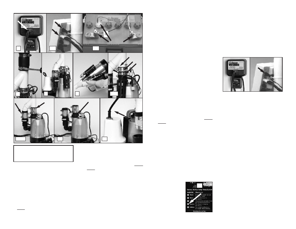
1. Unplug the primary pump from the blue
controller.
2. Remove the charger plug from the back of the
yellow controller.
3. Unplug the backup pump from the back of the
yellow controller.
4. Remove the sensor from the battery.
5. Remove the battery wires from the battery
terminals. Be sure they do not touch each
other while one is connected to the battery.
6. Slowly loosen the rubber union on the top of
the combination pump assembly to separate
the pipes. The water trapped in the pipe will
pour out into the sump as the rubber union is
loosened.
7. Separate the pump assembly from the rubber
union and lift it out of the sump by the
handle on the primary pump.
8. Turn the assembly up side down over the
sump pit to allow the remaining water in the
system to drain.
9. Loosen the hose clamp on the caged float
switch and remove the float switch.
10. Cut the cable ties on the backup float switch
and remove it.
11. Loosen the hose clamp on the top of the no-
hub connector on the primary pump.
12. Loosen the hose clamp on the top of the no-
hub connector on the backup pump.
13. Remove the Y-connector.
14. Unscrew the primary pump check valve.
15. Carefully slide the backup pump and bracket
out of the handle of the primary pump. Now
reverse the process.
16. Carefully slide the backup pump and bracket
into the handle of the new primary pump.
17. Screw in the check valve on the top of the
primary pump. (You can use the existing
check valve, or preferably replace it with a
new one.)
18. Connect the Y-connector to the top of the
check valve with the no-hub connector and
tighten the hose clamp.
19. Connect the backup pump to the other side
of the Y-connector with the other no-hub
connector.
20. Replace the caged float switch by tightening
it with its hose clamp.
21. Replace the backup pump float switch using 2
new cable ties. Make sure the float moves
easily, and will not get hung up on the pump.
22. Lower the pump back into the pit by the
handle of the primary pump.
23. Connect the top of the system to the rubber
union and tighten the hose clamp.
24 Connect the battery cables to the battery
terminals, WHITE to the NEGATIVE (-) post,
and BLACK to the POSITIVE (+) post.
25. Insert the fluid sensor into the top of the
battery.
26. Plug the backup pump into the back of the
yellow controller.
27. Plug the charger into the back of the yellow
controller.
28. Plug the primary pump into the blue
controller.
4
System
This green light should
always be flashing. It
indicates that the
system is operating,
and the battery is
connected. If this
light is off:
• Check the charger. Make sure it is securely
plugged into the wall outlet.
• Check the charger plug that fits into the rear
panel of the control unit. Make sure it is
securely plugged into the control unit.
• If all connections are secure and the wall
outlet is operating, but the POWER warning
light is flashing, replace the charger. Call
Glentronics parts department at 800-991-
0466, option 3.
5
Battery
This light and alarm will go on when the control
unit senses that the battery has approximately
1/2 hour of continuous pumping energy left.
This alarm cannot be silenced. It indicates that
your battery is discharged or defective and
immediate action needs to be taken to replace
the battery or clean the terminals. This alarm
will sound when:
• Corrosion on battery terminals and/or cable
rings is preventing the battery from charging
properly
• The battery is getting old and should be
replaced
• The pump has been running for many hours
and the battery is discharged
Check the battery cables and the battery terminals
for corrosion. Clean and tighten them as needed.
The procedure is described on the following page.
If the battery alarm goes on while the pump is
running and the power is out, you will have a
minimum of 1/2 hour of pumping time to replace
the battery. (In most cases, the pump does not
run continuously, and therefore, you actually
have a longer time to replace it.) You will not
be able to silence the alarm. Left unattended,
the basement will flood. In a severe emergency,
Page 9
1
REMOVE
4,5
11,12
14
15
2,3
7
6
8
9,10
SLIDE
OUT
YOU WILL BE DISCONNECTING ALL THE
WIRES. BE SURE THEY DO NOT FALL INTO THE
SUMP PIT. SEE DIAGRAM ON PAGE 12 FOR
PARTS DESCRIPTION.