Electrical diagram (bottom view) – Amico Ceiling Column Rigid (Stationary) User Manual
Page 8
*Please Select One of the Following:
Amico recommended circuit schedule based on layout
Custom circuit schedule. Please specify on circuit chart
Receptacle Type:
US/CAN
*BRITISH
(simplex only)
*GERMAN
(simplex only)
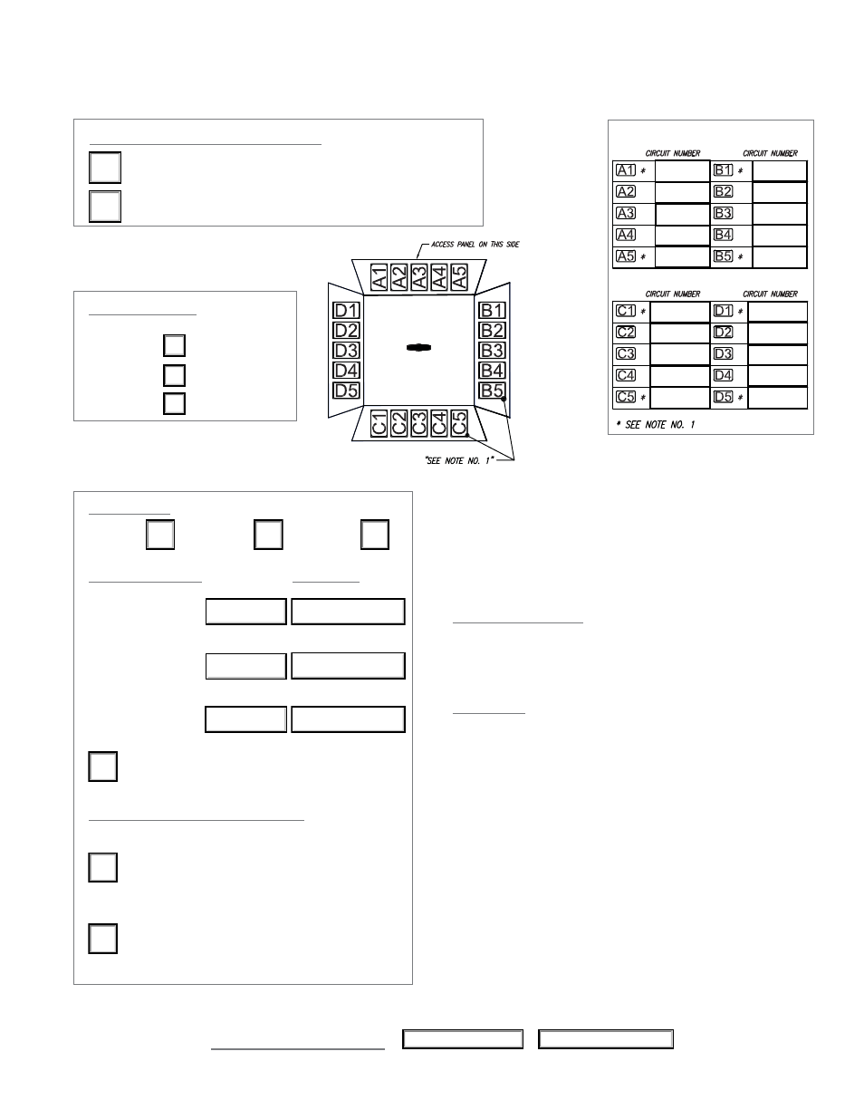
Circuit Chart
Electrical Diagram (Bottom View)
Approval Signature
Date
Phone No.
NOTE:
1.
Two electrical/communication/medical gas devices
cannot be placed together at any corner.
2.
If type of wire & gauge is not specified, Amico
will use the following:
For US/International
LIVE/HOT - 12 Ga. THHN Wire Black
NEUTRAL - 12 Ga. THHN Wire White
GROUND - 10 Ga. THHN Wire Green
For Canada
LIVE/HOT - 12 Ga. RW90 Wire Black
NEUTRAL - 12 Ga. RW90 Wire White
GROUND - 10 Ga. RW90 Wire Green
3.
Conduit: 1/2” [12.7mm] rigid EMT.
3/4" rigid EMT for low voltage provision.
4.
All conduits and wires will extend a minimum of12”
[304.8mm] above fi nish column for connection
to riser plate.
5.
A pull-string will be provided to be connected by
others for all ground jacks and data provision.
6.
British or German Receptacle cannot be positioned
side by side ie: A1 and A2.
*Please specify electrical details:
Type of wire:
THHN
XHHW
RW90
AWG Wire Gauge:
Wire Color:
10 & 12 LIVE/HOT
10 & 12 NEUTRAL
10 GROUND
Isolated
Power
Please select one of the following
All receptacles shall be mounted with
ground
pin
“DOWN”
All receptacles shall be mounted with
ground pin “UP” (Default)
www.amico.com
7
____ gauge
____ gauge
_______________________
_______________________
10 gauge
Green