Great Plains YP2425A-3620 36 Row 20-Inch Quick Start User Manual
Step 1: pre-programming preparation, Step 4: row status/row width setup, Step 2: change user level to dealer level
Quick Setup Guide for IntelliAg Model YP24 20” Air Pro
11001-1521-200908
©2009 DICKEY-john Corporation
Specifi cations subject to change without notice.
STEP 1: Pre-Programming Preparation:
Power on vehicle via ignition switch to activate Virtual Terminal (VT). Main menu will display pre-programmed default settings.
If errors are detected (e.g., failed sensors, incorrect confi guration) an alarm and code displays. Alarms are silenced by pressing the Alarm Cancel button
. Refer to Operator’s
manual for troubleshooting assistance.
The system has three user levels. The system loads in User Level 1 (operator level) at every power cycle. Access to User Level 2 and 3 screens to setup constants (system confi gura-
tion) requires a password.
1.
2.
3.
The Quick Setup Guide assumes the Virtual Terminal, Master Switch, Working Set Master Module, Working Set
Member Module, and all sensors have been connected and properly installed. Reference Operator’s manual
for installation instructions. NOTE: The master switch is only required for hydraulic control systems.
Reference the manual for instructions to assign a master switch as an auxiliary input.
STEP 3: Auto Confi guration (Identifi es sensors connected to each module)
Auto confi g is performed at the factory, but may need to be done in the fi eld as changes are
made to the system or if options are added to the base planter.
Verify Auto Confi g results are correct. Check that the correct number of rows are assigned to the
correct module and number of hopper sensors are assigned accurately.
To Run Auto Confi g:
Press the Next Page button
until the Module Confi guration button appears.
Press the Module Confi guration button
.
Press the AUTO CONFIG button
.
Hour glass will indicate system is being confi gured detecting the presence of seed or hopper
sensors connected to each module and will be automatically assigned to the appropriate
module.
When Auto Confi g completes, press the Row Assign button
to display the Row Assign-
ment screen to verify correct Row # is assigned to the correct module based on serial number.
Enter # of rows assigned to each module.
1.
1.
2.
3.
4.
5.
6.
STEP 4: Row Status/Row Width Setup
At the Row Assignment screen, press the Row I/O button
.
Begin entering desired values using Table A as reference.
Press the Work Screen button
when Row Status/Row Width confi gurations are com-
plete to return to the Main Work screen.
1.
2.
3.
TABLE A:
Row Status/Row
Width Setup
Default Value
or Value to
Enter
Instructions/Defi nitions
Row Width
20”
Enter row width distance in inches to calculate seed
rate correctly. NOTE: Using 15” planter in 30” mode
should change On/Off Pattern to Every 2nd Row Off.
Auto Update Width
Enabled
When enabled, implement width will automatically
calculate. If disabled, manually enter implement
width.
On/Off Pattern
Every Row On
On/Off Pattern indicates specifi c row patterns to
be on or off. Select pre-defi ned planter All Row On
pattern. For other pre-defi ned planter patterns or in-
dividual row settings, reference Operator’s manual.
Pop/Block Pattern
Every Row
Population
Determines which sensors are used to calculate
population and those used only for blockage detec-
tion. Select pre-defi ned Every Row Population. For
other pre-defi ned patterns, reference Operator’s
manual.
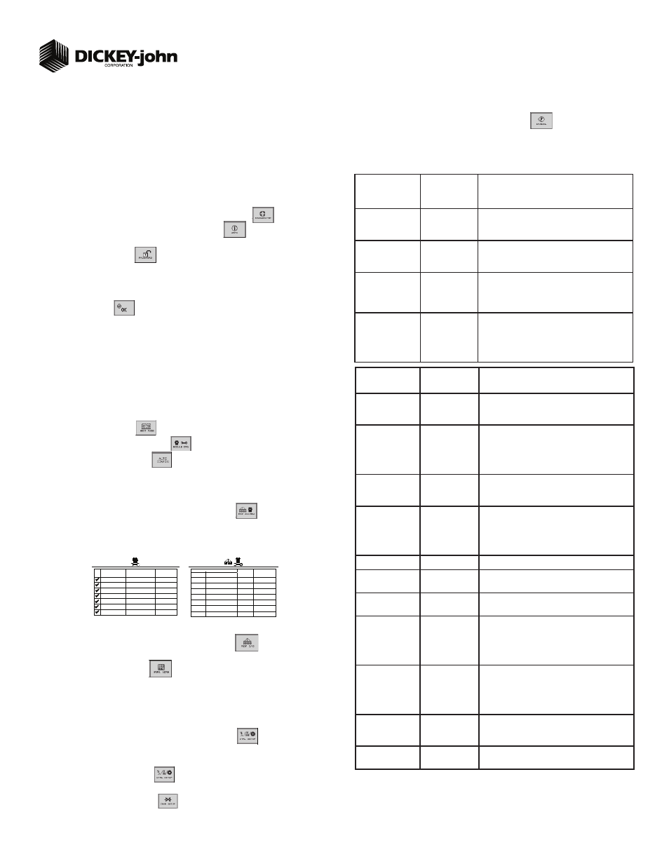
1
S E R I A L
N U M B E R
1
M O D U L E
T Y P E
M O D U L E
A D D R .
WSMB-POM
WSMB-POM
2
WSMB-18R
3
10001
10001
10002
WSMT-GY
WSMB-Rows
WSMB-POM
WSMB-CFM
10001
10002
10003
10001
4
5
6
7
# O F
R O W S
MODULE
ADDR.
TYPE
R O W
# ’s
1 5 - 2 2
1
WSMB-18R
2
WSMT-GY
8
14
1- 14
3
WSMB-Rows
1 4
2 3 - 3 6
Module Configuration Screen
Seed Sensor Configuration Screen
optional
optional
STEP 2: Change User Level to Dealer Level
To change the user level, a 6-digit password is required. Password includes the fi ve-digit se-
rial number found on the label of the Working Set Master or Information screen.
On the IntelliAg Main Work screen, press the Diagnostics button
.
At the Diagnostics screen, press the Information button
.
At the Information screen, record serial number of WSMT.
Press the Password button
.
On the Password screen, enter the 6 digit password as follows: enter the fi rst digit as 2 for User
Level 2. For the next fi ve digits, enter the Working Set Master serial number taken from the
WSMT or Information screen.
Press the OK button
. “Dealer screens on” appears at the bottom of screen confi rming the
password and dealer screens are activated.
Press the Work Screen button to return to the Main Work screen.
1.
2.
3.
4.
5.
6.
7.
STEP 5A: Material Confi guration Setup (Controlled Hydraulic Drive)
15 different materials can be confi gured for use as planter controls. Reference the System Con-
fi guration section in the Operator’s manual for additional information.
At the Main Menu screen, press the Control Setup button
.
Select and press one of the Material buttons (Material 1-15).
Enter desired values from Table B1.
Press the Control Setup button
to return to the Control Setup screen.
Repeat steps 2-4 for additional materials.
Press the Channel Setup button
to proceed to channel setup screen.
1.
2.
3.
4.
5.
6.
TABLE B1:
Material Setup
Default Value/
Value to Enter
Controlled Hydraulic Drive
Instructions/Defi nitions
Matrl Label
Matrl 1
Material Name can be customized to accurately
defi ne the material’s type. Creating a name allows
for quick identifi cation at the Control Setup screen.
Type
Planter Control
Desired type of application control channel being
used for a specifi c material. The Material Type must
correctly match the Control Type to be able to select
Material from the Material Summary screen and
operate properly.
Units
Ks/Ac
S/Sec
Automatically changes with the type of material
application selected. Changes units for target
application.
Preset Method
Enable
Enabled Preset Method allows 10 user-defi ned tar-
get rates to be adjusted from the Main Work screen
using Inc or Dec buttons. A Disabled Preset Method
increases/decreases the target rate based on the %
values set at the Material Setup screen.
Seeds per Rev
See Manual
Set to number of seeds per 1 disc revolution.
Disc Low Limit
(Air Pro)
5
Set to desired min seed disc RPM.
Disc High Limit
(Air Pro)
37
Set to desired max seed disc RPM.
High Pop Alarm
15%
This is the percentage above the target population
of the planter channel if rows are assigned to the
planter channel. If rows are not assigned to a
planter, this is the percentage above average planter
population for all unassigned rows.
Low Pop Alarm
15%
This is the percentage below the target population
of the planter channel if rows are assigned to the
planter channel. If rows are not assigned to a planter
channel, this is the percentage below average
planter population for all unassigned rows.
Product Level
Alarm
Sets the level to trigger an alarm alerting of low
product levels. Entered value is an estimate in
volume.
Row Fail Rate
2/1 (2 seeds
every 1 second)
Set to desired number of seeds per second to trig-
ger seed sensor failure alarm.