4 hitching up, 5 air brake coupling procedure – Great Plains P16843 Serial No 18009001 User Manual
Page 16
Simba SL
Operating Instructions
16
2.4 Hitching Up
2.4.1 Hitching up a Tractor
to the SL / Preparing for
Transport
When hitching-up the machine,
ensure that no-one is between the
tractor and the machine.
When the SL is parked for extended
periods of time it should ideally be
left in the unfolded, i.e. work position
for stability, safety and ease of
access for maintenance. However,
parking the SL in the folded position
(ensuring the transport lock is
engaged) is acceptable in the
normal course of operation.
Tractor Oil Flow Adjustment:
As a general rule the tractor oil flow
rate should be set in the lowest
setting before starting. This can then
be increased to allow the desired
rate of operation as applicable. This
will minimise excessive oil flow and
consequent power usage and heat
generation.
1.
Reverse the tractor up to the bar coupler
and engage the link arms.
2.
Ensure the tractor hydraulics are
depressurised and in the locked or
closed (not float) setting. Ensure the
axle taps are closed.
3.
Couple the hydraulic hoses to the tractor
ensuring that the two wing hoses
(yellow) are together and the lift cylinder
hoses (red) are together. There is also
a single hose (blue) to control the wing
lock.
4.
Raise the front of the machine and move
the parking stand to the work position.
5.
If the machine is already folded it is now
ready for transport. If the machine is
unfolded please refer to 2.5.2.
Ensure that the wing lock is engaged
correctly before transporting the
machine.
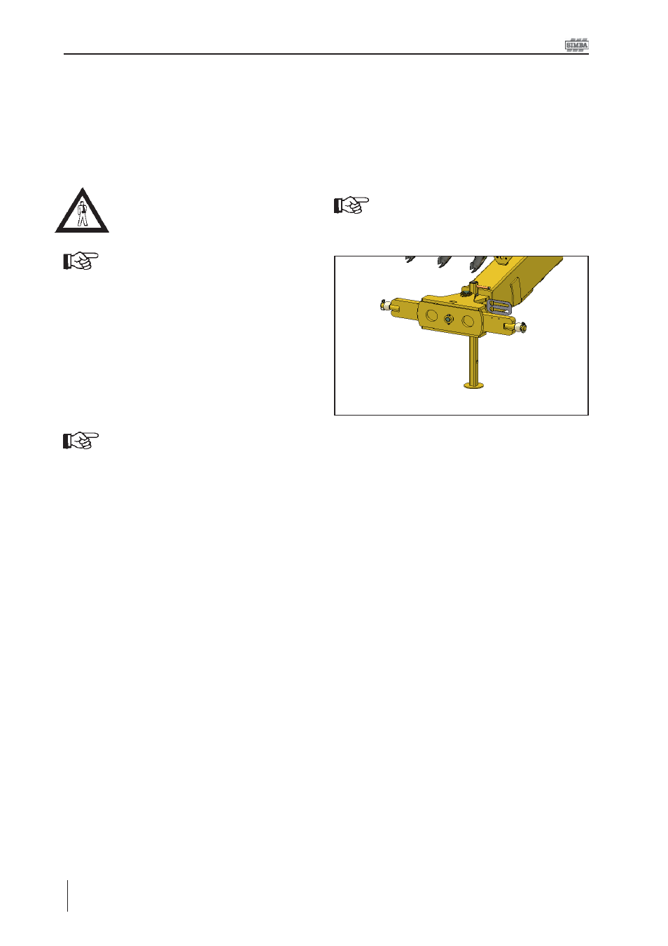
2. Transportation / Installation
Fig. 2.01: Bar Coupler
2.5 Air Brake Coupling
Procedure
Please refer to the following procedure when
coupling or decoupling any item of SIMBA
machinery fitted with an AIR brake or AIR and
HYDRAULIC brake system. Please note that
this procedure does not apply to any
machines fitted with a HYDRAULIC system
ONLY.
2.5.1 When Coupling
1.
Reverse up to the machine and connect
the machine to the tractor as instructed
to in Section 2.4.1.
2.
With the machine connected couple the
air lines. When coupling ensure the
yellow line is attached first followed by
the red line.
3.
Your brake hoses are now attached and
are ready for operation.