System component installation, Clutch control, Tractor harness – Great Plains 3PYP-32TR30 32 Twin Row 30-Inch Quick Start User Manual
Page 5
Quick Setup Guide for IntelliAg Model 3PYP 32 Row Twin Row
11001-1427D-201209
©2012 DICKEY-john Corporation
Specifi cations subject to change without notice.
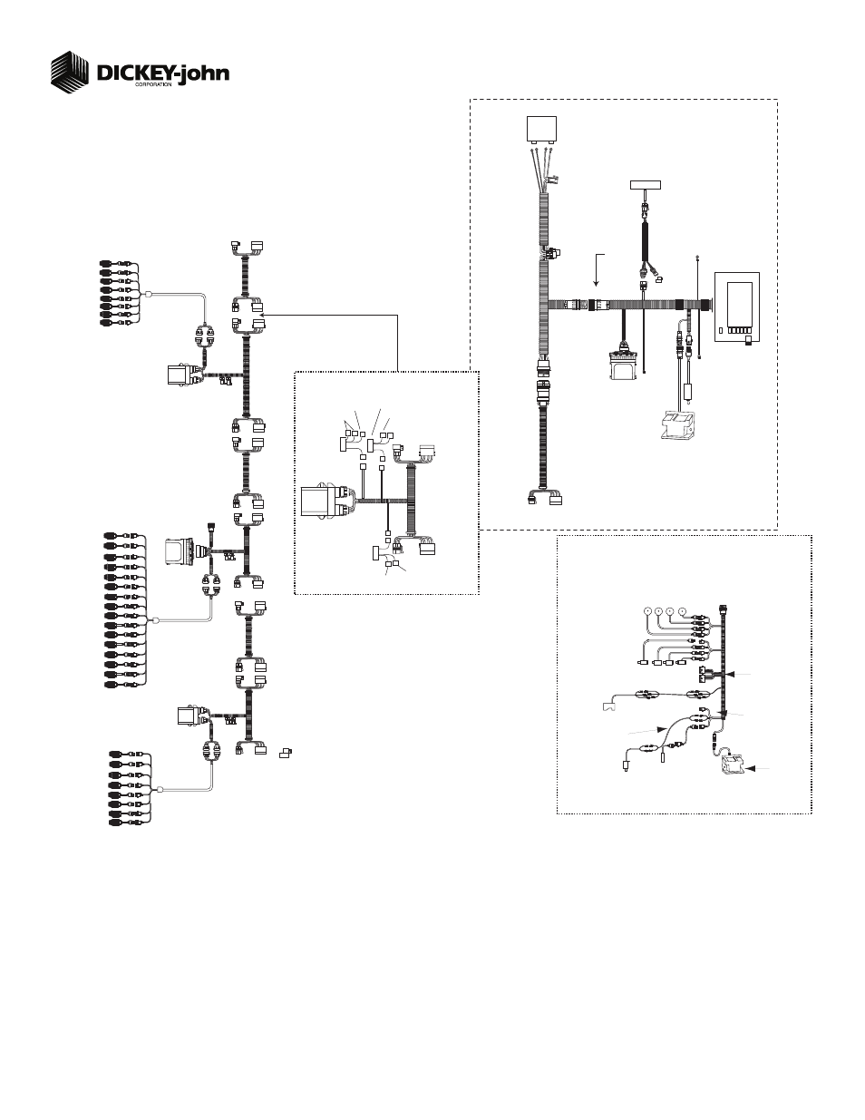
System Component Installation
Locate and install system components as shown in
the diagram. Note how the modules are identifi ed
and which modules are located on which sections in
this system.
Connect WSMB module harnesses together with
included extensions. Modules connect to the WSMT
harness connection. Plug all unused connectors with
included dust plugs.
Secure any excess wires with tie-wraps.
See Operator’s Manual for additional installation
information.
Power on monitor and program with correct con-
stants as described on this Quick Start Guide.
1.
2.
3.
4.
5.
5
Row 5
467980143
Extension
Harness 25’
WSMB Module
Harness
467981201A
WSMB
Module
Seed Monitor
467981100S1
467980143
Extension
Harness 25’
WSMT
Module
Harness
467980151
Connect to
Actuator
Harness
467980160
467980143
Extension
Harness 25’
Can
Terminator
Connect Cab Harness
to Implement Can
Harness
Radar Speed Sensor
467833000S1
(Radar connected to either
tractor harness or WSMT
as shown below)
Virtual
Terminal
Chassis
Ground
CAN
Terminator
467980126
Ignition
Connect to
switched +12VDC.
NOTE: This wire
must be connected to
switched +12VDC
Master
Switch
(467980124S1)
+
-
Tractor Cab Harness
467980455
Battery
CFM
Tractor ECU
Controller
(467985060S1)
Harness
467980452
(5” Terminal) or
Harness
467980451A
(10” Terminal)
467984210S1
Tractor Harness
RS232
GPS
(467980451 Harness)
Implement CAN
Breakaway Harness
467980132
Connect to Optional
Hydraulic Tongue Harness
or to Extension
Hopper
Extension Harness
466820714
Accessory Sensors
connection to WSMT
ACTUATOR HARNESS
467980160
Application
Rate Sensors
(Channel 1-4 Feedback)
Labeled FB1-FB4
PWM Solenoid
Valves
Channel 1-4
Control
Implement Lift Sensor
464820520S1
If no implement lift
sensor is used, connect
the IMP LIFT leads
together
Fan/Shaft
RPM Sensor
466970014S1
Radar Speed Sensor
467833000S1
(Radar connected to
either tractor harness
or WSMT as shown below)
Servo Valves
(Labeled Servo 1
and Servo 2)
Actuator Harness
467980160
Test Switch
Note: Connect the WSMT
Actuator Harness and the
Dj Planter Harness to the
mating connectors of the
WSMT Module Harness
Connect to Harness
467980132
Output 1 Left Clutch
464820523S1
Output 1
Marker Tilt
Output 2
Marker Fold
Planter
Output
Module
464820511S1
467983504
467982000S1
Clutch
Control
Output 2 Center Clutch
Right
Clutch
Output 1
464820512S1
Output 2
Wing
Fold
Implement
Lift Extension
Harness
466820713
WSMT II
467980815S1
CFM
Harness
467980330
WSMB
Module
WSMB
Module
Harness
467981201A
Seed Monitor
467981100S1
Fan
Extension
Harness 15’
459680922
Hopper
Level
Sensor
Row 5
Row 2
Row 3
Rows 1- 8
Left Section
Rows 9-24
Middle Section
Row 22
Row 23
Row 24
Right Section
Rows 25-32
Row 25
Row 26
Row 27
Row 4
Row 10
Row 11
Row 12
Row 28
Row 1
Row 6
Row 13
Row 14
Row 15
Row 16
Row 17
Row 18
Row 29
Row 7
Row 8
Row 9
Row 19
Row 20
Row 21
Row 30
Row 31
Row 32