Quick setup guide for intelliag model yp24 70 cm, Step 8: speed set calibration setup, 3step 10: clutch folding module (cfm) setup – Great Plains YP2425F-2470 Quick Start User Manual
Page 3: Step 9: accessory sensor setup
Quick Setup Guide for IntelliAg Model YP24 70 cm
11001-1433C-200907
©2009 DICKEY-john Corporation
Specifi cations subject to change without notice.
STEP 8: Speed Set Calibration Setup
At the Main Work screen, press the Speed Set button
.
Enter desired values using Table E as reference.
Press the Work Screen button
when ground speed calibration confi gura-
tions are complete to return to the Main Work screen.
1.
2.
3.
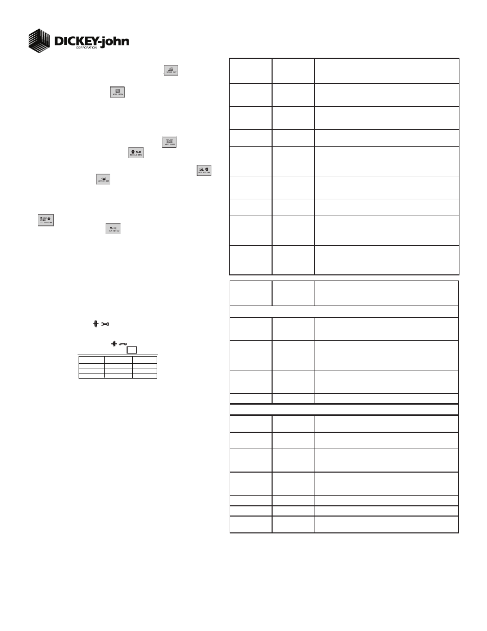
TABLE E:
Speed Set
Default Value
or Value to
Enter
Instructions/Defi nitions
Source
Digital Frequency
Select CAN Ground if radar is connected to ISO tractor cab har-
ness. Select Digital Frequency if radar or hall-effect is connected to
WSMT actuator harness.
Gspd Constant
12192
Input based on pulse count produced by the ground speed sensor
over 400’ distance. See Operator’s manual for calibration instruc-
tions.
Shutoff Speed
0.8 kph
Set desired minimum ground speed allowed before the system
shuts off.
Minimum
Override
3.2 kph
Set to operate when actual ground speed falls below the designated
value. Control will operate at this speed until actual ground speed
rises above minimum override speed or actual speed drops below
shutoff.
Master Sw
Timeout
10
Set to desired number of seconds system shuts off if the master
switch is turned on and there is no ground speed. Toggle master
switch to restart the system and turn off alarm.
Gspd Fail Alarm
Delay
5
Set to desired number of seconds alarm sounds after the ground
speed is zero and seed fl ow continues. (Monitor only)
Precharge
Ground Speed
0
Set to the desired speed the system will use when a precharge time
has been enabled for a control channel. Refer to Table C1: Planter
Control Setup for Precharge Time. This setting will only display
when a Precharge Time has been entered.
Implement Lift
Enabled
Implement lift switch, when enabled, displays an implement lift
indicator on the Main Work screen indicating implement lift position
as up or down. Control channels can be turned on and off without
using the master switch.
3
STEP 10: Clutch Folding Module (CFM) Setup
The CFM is installed in the cab to control row clutches, marker, fold, fertilizer on/off,
lift and hitch.
At the Main Work screen, press the Clutch CFG button to access the Clutch
Confi guration screen and verify that the correct # of clutches are confi gured for
the system.
The Clutch CFG button
only appears as a top level button when a planter
output module and clutch folding module are installed.
1.
2.
STEP 9: Accessory Sensor Setup
Hopper Assignment
At the Main Work screen, press the Next Page button
.
Press the Module Confi guration button
to display the Module Confi guration
screen.
At the Module Confi guration screen, press the Hopper Assign button
.
Press Hopper Set button
.
Enter desired values using Table F as reference.
RPM Assignment
At the Module Confi guration screen, press the Accessory Assignment button
.
Press the RPM Setup button
.
Enter desired values using Table F as reference.
For additional information regarding Hopper Level Sensor and Shaft/Fan Sensor
setup, reference Operator’s manual.
1.
2.
3.
4.
5.
6.
7.
8.
TABLE F:
Accessory
Setup
Default Value
or Value to
Enter
Instructions/Defi nitions
Hopper Setup
# of Hoppers
2 (base unit)
2 more (optional)
# of hopper sensors connected to each module. # of hopper data
items for each listed module and the Hopp #’s value will automati-
cally populate if Auto Confi g is used to confi gure installed sensors.
Hopper Logic
Level
Active Lo
Sets the active state to low signifying that an alarm is generated
if the sensor’s output is in a low state. Use this setting if the con-
nected sensor outputs a low condition when empty similar to the
DICKEY-john hopper sensor.
Hopper Alarm
Delay
5 sec
Controls the delay time between the detection of a high/low hopper
alarm condition and the generation of the resulting alarm. The value
is entered in seconds.
Channel
Assigns hopper sensor to channel
RPM Setup
High Alarm (fan
speed)
4200 rpm
Sets the RPM value at which a high RPM warning error is gener-
ated.
Low Alarm (fan
speed)
2900 rpm
Sets the RPM value at which a low RPM warning error is generated.
High Alarm Delay
10 sec
Establishes the delay between the detection of a high RPM alarm
condition and the resulting alarm display. The value is entered in
seconds.
Low Alarm Delay
10 sec
Establishes the delay between the detection of a low RPM alarm
condition and the resulting alarm display. The value is entered in
seconds.
RPM Constant
3 pulses/rev
Number of pulses per sensor revolution.
RPM Filter
0
Filters the signal out of the RPM sensor.
Disable Control
on Low Alarm
Disabled
Allows for disabling of all Control Channels if the RPM value of the
selected sensor falls below the low alarm level setting.
O U T P U T
1 - 9
# O F
R O W S
R O W
# ’ s
1 0 - 1 5
LEFT
CENTER
9
6
1 6 - 2 4
RIGHT
9
# of Clutches
3