Great Plains 3N-3020 Operator Manual User Manual
Page 39
3/29/2012
196-366M
37
Adjustments
Side Gauge Wheels 20 Series Openers
Refer to Figure 20
The side gauge wheels have two, interrelated
adjustments:
• angle of side gauge wheel, and
• distance between side gauge wheel and row
unit disk.
Refer to Figure 21
Adjust side-gauge-wheel angle so the wheels
contact the row unit disks between 4 and 8 o’clock
at the bottom of wheel.
At the same time, keep the side gauge wheels
close to the opener disks so openers do not plug
with soil or trash but far enough out so the disks
and wheels turn freely.
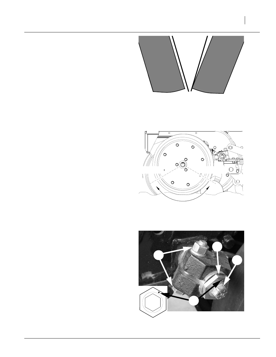
Refer to Figure 22
To adjust side gauge wheels:
1.
Raise drill slightly to remove weight from side
gauge wheels.
2.
Loosen hex-head bolt (1). Move wheel and
arm out on o-ring bushing.
3.
Loosen pivot bolt (2). Turn hex adjuster (3) so
roll pin (4) is at 1 o’clock. Use this as the start-
ing point for adjustment.
4.
Move wheel arm in so side gauge wheel con-
tacts row unit disk. Tighten hex-head bolt (1)
to clamp arm around bushing and shank.
5.
Check the wheel-to-disk contact. Lift wheel
and arm. When let go, the wheel should fall
freely.
• If wheel does not contact disk from 4 to 8
o’clock, move hex adjuster until wheel is an-
gled for proper contact with disk.
• If wheel does not fall freely, loosen hex-
head bolt (1) and slide wheel arm out just until
wheel and arm move freely. Retighten hex-
head bolt.
6.
Keep turning hex adjuster and moving wheel
arm until the wheel is adjusted properly.
When satisfied, tighten pivot bolt to 110 foot-
pounds. Tighten pivot bolt (2).
Side Gauge
Wheel
Side Gauge
Wheel
Opener
Disks
Incorrect
Correct
Figure 20
Side Gauge Wheels
17812
Figure 21
Wheel-to-Disk Contact Area
8 o’clock
4 o’clock
Figure 22
Side Gauge Wheel Adjustment
Starting Point
18450
2
1
3
4
Note: Wheel touches at bottom and gaps open 3/8” to
5/8” at top.