8 pro-lift trip-reset tine hydraulics – Great Plains SLD350 Operator Manual User Manual
Page 32
32 Simba SLD
602-262M-ENG
2013-07-25
5.8 Pro-Lift Trip-Reset
Tine Hydraulics
The circuit allows for the tines to be
pressurised down into work, whereupon a
relief valve limits this applied tractor down
pressure to a value less than the main system
accumulator (80b x 2 litre). This allows tines
to trip in work, the oil being absorbed by
the main accumulator. A secondary (rod
side) accumulator ensures this side of the
cylinder is maintained full of oil to minimise
cavitation and seal damage. A pre charge
valve restricts return rod side oil flow to the
tractor as the tines are pressurised down
to ensure this secondary circuit is charged.
In operation, oil is locked in the cylinder
circuit at a pressure determined by the relief
valves 90-120 bar full bore side and 0-20 bar
rod side. This occurs at all times, even with
the circuit in float at the tractor, provided the
tines are fully down. For extremely stony
conditions, adjust the valve to read 90 bar
on the gauge as the tines are pressured
down. For heavy soils with little stone
where compaction is present it is possible
to increase this pressure to 120 bar.
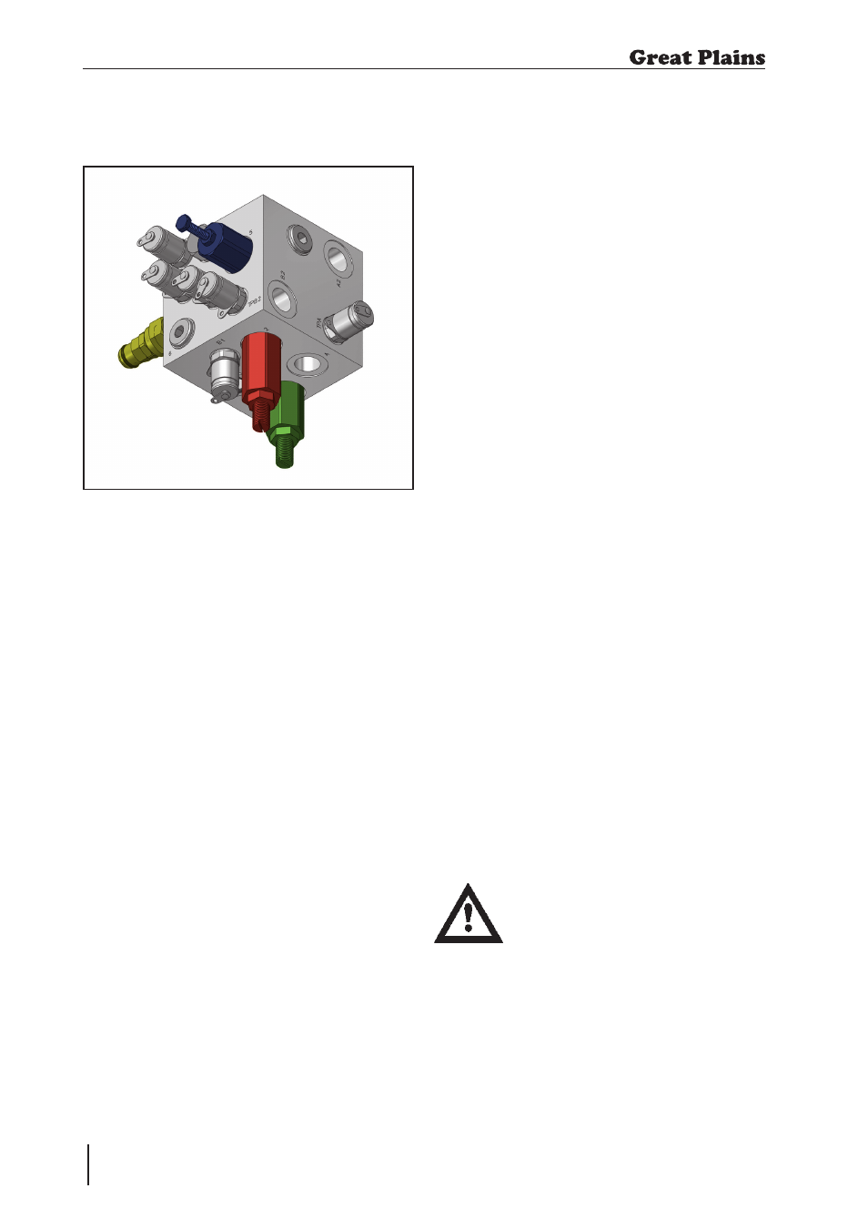
Fig. 5.05: Pro-Lift Tine Hydraulic Manifold
5. Servicing and Maintenance
If the tine circuit should need setting the
following procedure should be followed (an
assistant will be required):
1. Raise machine, to ensure tines are fully
clear of the ground at depth.
2. Adjust relief valve (
marked 1 /
coloured green) clockwise fully. Turn
anticlockwise one full turn.
3. Adjust flow control (
marked 5 /
coloured blue) fully clockwise, then
anti-clockwise 4 turns.
4. Adjust accumulator relief valve
(
m a r k e d 2 / c o l o u r e d r e d )
anticlockwise fully. Turning clockwise
now will increase the pressure on the
top gauge.
5. Remove cap from sequence valve and
remove the anti-tamper pin. Loosen
anticlockwise fully and then tighten
clockwise until slight resistance is felt.
6. Pressure tines down and further adjust
sequence valve (
marked 3 / coloured
yellow) until bottom gauge reads
10-20 bar.Lock with lock nut and refit
anti-tamper pin and cap.
7. Continue to hold pressure in tine
circuit and set accumulator relief (
2) to
between 90 and 150 bar (see section
5.9.1) as tines are lowered.
If tines do not relieve under severe
overload, this valve should be
reduced (anti-clockwise) until this
occurs in work, otherwise damage
may occur.
8. Put main circuit in float, check that
pressure is maintained.