Great Plains Simba Double Press 2013 Operator Manual User Manual
Page 20
20
Simba Double Press
610-026M-ENG
2013-01-25
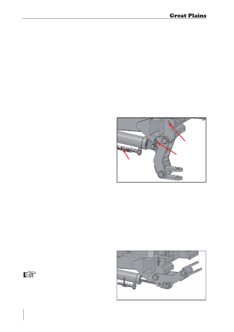
2.7.4 Rear Drawbar Setting
To prepare the rear drawbar for use:
1. Open the tap on the rear drawbar
cylinder.
2. Retract the cylinder and insert pin.
3. Close the tap to secure its position.
To change back to road transport /
'not in use' position:
1. Open the tap on the rear drawbar
cylinder.
2. Remove the pin and stow in the hole
shown.
3. Extend the cylinder and close the tap
to secure its position.
2.7.2 Transporting a Press
Towed Behind a Disc Cultivator
With both machines in the transport position
i.e. raised and folded, the chassis of the disc
cultivator should be slightly nose down or
horizontal even when the downward load
from the Double Press is applied to the
drawbar of the disc cultivator. The chassis
should NEVER be tail low in transport as
this will give a high negative loading on the
tractor which could lead to loss of traction
to the rear wheels.
Extreme caution must be taken when the
Double Press is transported up steep
gradients and across side slopes. Higher
drawbar loading can be achieved by
shortening the drawbar cylinder.
Prior to leaving the field to travel on a public
highway ensure that any clods of soil are
removed from the machine to prevent them
from fouling the road.
MAXIMUM ROAD TRANSPORT SPEED 16
MPH (25 km/h).
2.7.3 Changing from Work to
Road Transport (Press Towed
Behind a Disc Cultivator)
1. Operate the hydraulics to raise the disc
and Double Press.
2. Operate the hydraulics to fold the
wings on both the disc cultivator and
the Double Press.
3. Fit the transport straps to both
machines.
It may be necessary to shorten
the drawbar cylinder of the disc
cultivator until the chassis is
horizontal or slightly nose down
before moving the machines.
Shortening the Double Press drawbar
cylinder will increase the loading on the rear
of the disc cultivator frame. If necessary this
can be used to level the chassis for road
transport.
2. Transportation / Installation
Fig. 2.04: Rear Drawbar position when in use
STOWAGE HOLE
PIN
TAP (SHOWN OPEN)
Fig. 2.05: Rear Drawbar position when not in use