Great Plains 24 Series Drills Assembly Instructions User Manual
General information, Assembly instructions, Folding markers
1
Installation Instructions
Great Plains Mfg., Inc.
© Copyright 1998 Printed 11/25/98
Used with:
•
•
•
113-672M
24 Series Drills
Folding Markers
2400
2410
2420
General Information
These instructions explain how to install the optional markers.
The markers fold and unfold hydraulically for field operation. The
marker disks leave a line for the drill operator to follow on the next
field pass. Markers are mounted on the drill frame and require
two hydraulic remote valves on the tractor. A sequence valve is
available so markers can be operated on one hydraulic circuit.
These instructions apply to:
113-662A
24FT 3PT DUAL MARKERS
113-466A
94 3PT SEQ VALVE KIT-FIELD
Manual Update
Refer to the drill operator’s manual for detailed information on
safely operating, adjusting, troubleshooting and maintaining the
markers. Refer to the parts manual for part identification.
• 2400, 2410 and 2420 Operator’s Manual. . . . . . .118-706M
• 2400, 2410 and 2420 Parts Manual. . . . . . . . . . 118-706P
Before You Start
Starting on page 4 are detailed listings of parts included in
the option packages. Use these lists to inven-
tory parts received.
Assembly Instructions
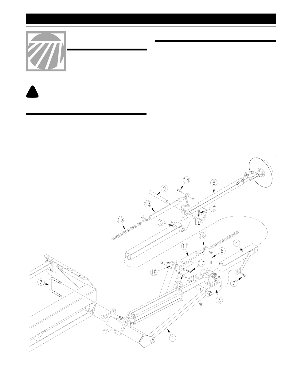
Marker Assembly
1.
Lower drill into field position. Allow 15 feet of clearance from
each end of drill box for marker assembly.
2.
Attach first marker section (1) to drill frame. Mount marker
as far out on drill frame as possible. Secure marker to drill
frame with 5/8-inch u-bolts (2), lock washers and hex nuts.
3.
Remove port plugs from marker cylinder and carefully un-
fold first marker section. Rotate hinge (3) into a horizontal
position.
4.
Assemble second marker section (4) onto first section so
that stop block (5) on second section faces up. Secure sec-
tions with 5/8-inch bolt (6) and lock nut and 3/8-by-2-inch,
grade 2 shear bolt (7) and lock nut.
IMPORTANT: Use a grade 2 bolt for the shear bolt or marker
damage will occur during field operation.
5.
Place third marker section (8) over end of second section
and insert hinge pin (9) through second- and third-section
pivot. Secure hinge pin with the 1/4-by-2-inch bolt (10) and
lock nut.
6.
Bolt chain pivot (11) to first marker section with 3/8-by-3 1/4-
inch bolt (12) and lock nut so chain pivot pivots freely on bolt.
7.
Bolt chain bar (13) to third marker section
with the 3/8-by-1 1/2-inch bolt (14) and
lock nut so chain bar pivots freely on bolt.
8.
Con-
nect
marker
chain
(15) to
chain bar
and chain
pivot with utility
clevis (16). With
marker disk adjusted
for seeding width and
disk touching the
ground, remove chain slack with
utility clevis nearest drill.
9.
Assemble full-threaded, 3/8-inch stop bolt
(17) and lock nuts on lift-arm extension (18) so
head of stop bolt extends as little as possible.
After the marker is bled and folded, adjust stop
bolt to remove slack from chain. Refer to Mark-
er Chain Adjustments, "Adjustments" in the
operator’s manual.
Figure 1
Marker Assembly
17628
When you see this symbol, the subsequent instructions and
warnings are serious - follow without exception. Your life and
the lives of others depend on it!
!!