Great Plains 705 Assembly Instructions User Manual
General information, Assembly instructions, Harrow option
1
Installation Instructions
Great Plains Mfg., Inc.
© Copyright 2000 Printed 4/25/2007
Used with:
•
•
116-109M Rev. A
EWNT7 and 705
Harrow Option
EWNT7
705
General Information
These instructions explain how to install the optional spring-tine
harrow. Mounted behind the drill, the harrow evenly distributes
crop residue in no-till conditions.
These instructions apply to:
116-072A
EWNT7 & 705 CPH HARROW
Manual Update
Refer to the drill operator’s manual for detailed information on
safely operating, adjusting, troubleshooting and maintaining the
spring-tine harrow. Refer to the parts manual for part identifica-
tion.
• EWNT7Operator’s Manual . . . . . . 150-082M-A or 150-082M
• EWNT7 Parts Manual . . . . . . . . . . . . . . . . . . . . . . 150-082P
• 705 Operator’s Manual. . . . . . . . . . . . . . . . . . . . . .150-213M
• 705 Parts Manual . . . . . . . . . . . . . . . . . . . . . . . . . . 150-213P
Before You Start
Page 3 is a detailed listing of parts included in the spring-tine har-
row package. Use this list to inventory parts received.
Assembly Instructions
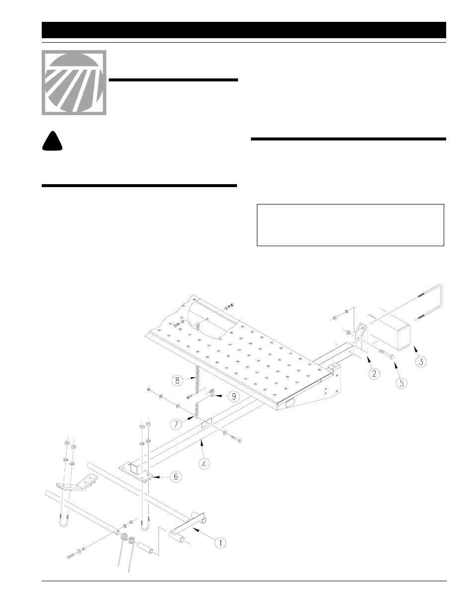
1.
Lower drill into field position. Place harrow frames (1) be-
hind drill.
2.
Mount hinge brackets (2) on 4-by-6-inch frame tube (3) on
drill. Position hinge brackets so harrow arms (4) will be close
to the ends of harrow frames. Center hinge brackets be-
tween drill openers.
Attach hinge brackets to frame tube using square u-bolts,
lock washers and nuts as shown.
3.
Install harrow arms (4) in hinge brackets so arms pivot on
1/2-inch bolts (5). Secure bolts with nylock nuts.
IMPORTANT: Position hinge brackets so drill openers do
not contact harrow arms during drill operation. Exact loca-
tion of hinge brackets on frame tube will differ with drill row
spacing.
Figure 1
Harrow Assembly
17868
When you see this symbol, the subsequent instructions and
warnings are serious - follow without exception. Your life and
the lives of others depend on it!
!!
4.
Place harrow frames under channels (6) on harrow arms.
Bolt harrow frames to harrow arms using round u-bolts, lock
washers and nuts. Leave u-bolts loose for harrow adjust-
ment.
5.
Bolt short support chain (7) to tab on top of harrow arms with
3/8-inch hex bolts, flat washers, lock washers, and hex nuts.
Bolt long support chain (8) to rib under walkboard using 3/8-
inch hex bolts, flat washers, lock washers and hex nuts.
6.
Connect support chains with chain clevis (9). Adjust chains
so both harrow sections are 152 mm (6 in.) above the
ground.