Initial preparation of the planter, Tractor preparation, Attaching the planter to the tractor – Great Plains 8030P G1021 Operator Manual User Manual
Page 8
60303P and 80303P Three-Point Planter 401-008M
5/15/06
6
Great Plains Mfg., Inc.
Section 2 Planter Operation
Section 2
Planter Operation
The following section was written to provide general in-
formation on the planter and tractor operation.
Initial Preparation of the Planter
•
Lubricate the planter and markers as shown in
“Section 6 Lubrication” on page 24.
•
Check the tires for proper inflation, refer to the Tire In-
flation Chart in "Section 9 Specifications" on
page 33.
•
Check the chains for proper tension and alignment as
shown in "Section 7 Maintenance" on page 28.
•
Perform all beginning of season and daily planter ser-
vice as discussed in “Section 8 Storage” on
page 30.
•
Check over the planter and replace worn or damaged
parts before going to the field.
•
All nuts, bolts and screws should be checked per the
Torque Value Chart in "Section 9 Specifications" on
page 33.
•
The legs of the cotter pins should be spread.
Tractor Preparation
For tractor front end stability additional tractor ballast
may be required. Add front ballast according to your
tractor's operator’s manual.
Attaching the Planter to the Tractor
For the planter to function properly, attach the planter to
the tractor in the following manner.
1.
Set the tractor wheels at double the planter row
spacing. Example: For a planter with 30" rows the
front and rear wheels should be set at 60" center to
center. This prevents soil compaction on the rows.
On hillsides and steep slopes set the wheels as wide
as possible for maximum stability.
Minium required draw bar horsepower for field work
6-row planter
60 - 90 HP
8-row planter
80 - 120 HP
Recommended Tractor Horsepower
NOTE: The tractor must have adequate 3 point hitch
lift capacity to lift the machine weight, attachments,
seeds and dry chemicals. Shipping weights, (refer to
“Section 9 Specifications” on page 31), do not in-
clude seed, dry chemicals or optional attachments.
2.
Adjust the tractor lower lift links to maximize lifting
height.
Set the tractor sway blocks to minimize side sway.
Position the lift controls in float position.
3.
Back the tractor up to the planter. Align the lower
links with the lower hitch holes on the planter. Insert
the hitch pins and the spacers, supplied with the
planter, according to the category of your tractor,
Figure 2-1. Lock the pins in place.
4.
There are two holes on the planter for the upper
hitch point. The the tractor’s top link should be at-
tached in the lower hole for Category II, see Figure
2-1. Some Category II quick couplers and all Cate-
gory III top links should be attached in the upper hole,
Figure 2-1. To attach the top link some adjustment
may be required.
5.
Raise the planter and look for any interference while
standing between the planter row units. Remove the
pin holding the parking stand and raise the stands to
the transport position. Put the pin in the lowest hole
in each stand, see Figure 2-1. Never work under a
raised Planter.
6.
On level ground, lower the planter onto the gauge
wheels. If the planter is not level see Leveling the
Planter page 7.
NOTE: To keep the planter level make sure that the
lower lift links are adjusted evenly.
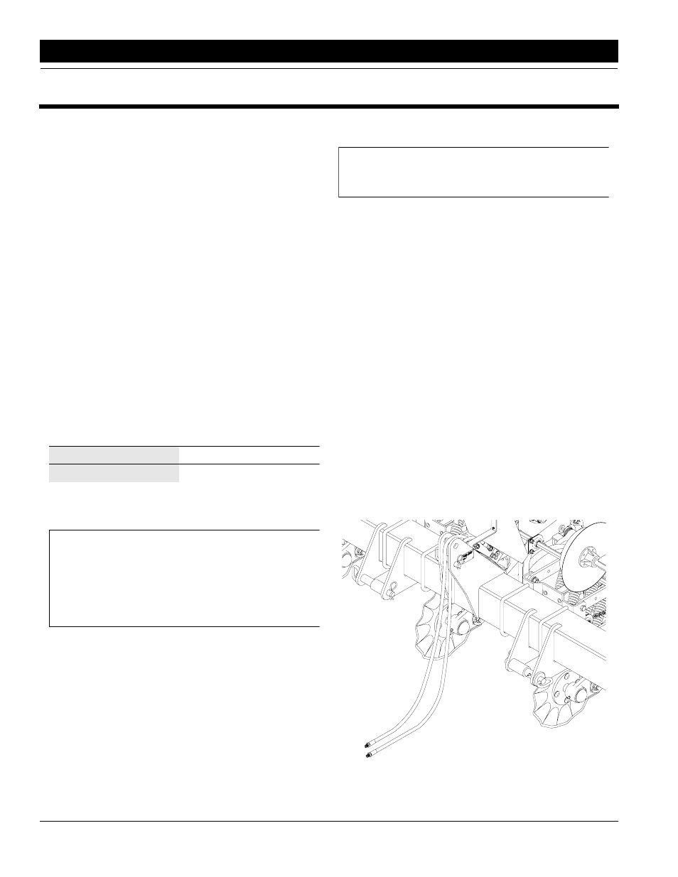
Hitch on Planter
Figure 2-1
12340