Assembly, Hub & wheel, Hitch – Great Plains 2551SC Predelivery Manual User Manual
Page 11: Assembly hub & wheel hitch
10/10/2013
540-179Q
Great Plains Manufacturing, Inc.
7
Assembly
Hub & Wheel
6.
After un-crating the machine, place the center frame in the
center of work area by setting the front on stands as
shown.
Refer to Figure 4
Note: All bolts are pre-installed on the unit in there proper loca-
tion. Bolts will need to be removed and then re-installed
during assembly. It is important to attach hub & wheel as-
sembly
, then hitch assembly
before attaching or folding wings because machine could
tip over.
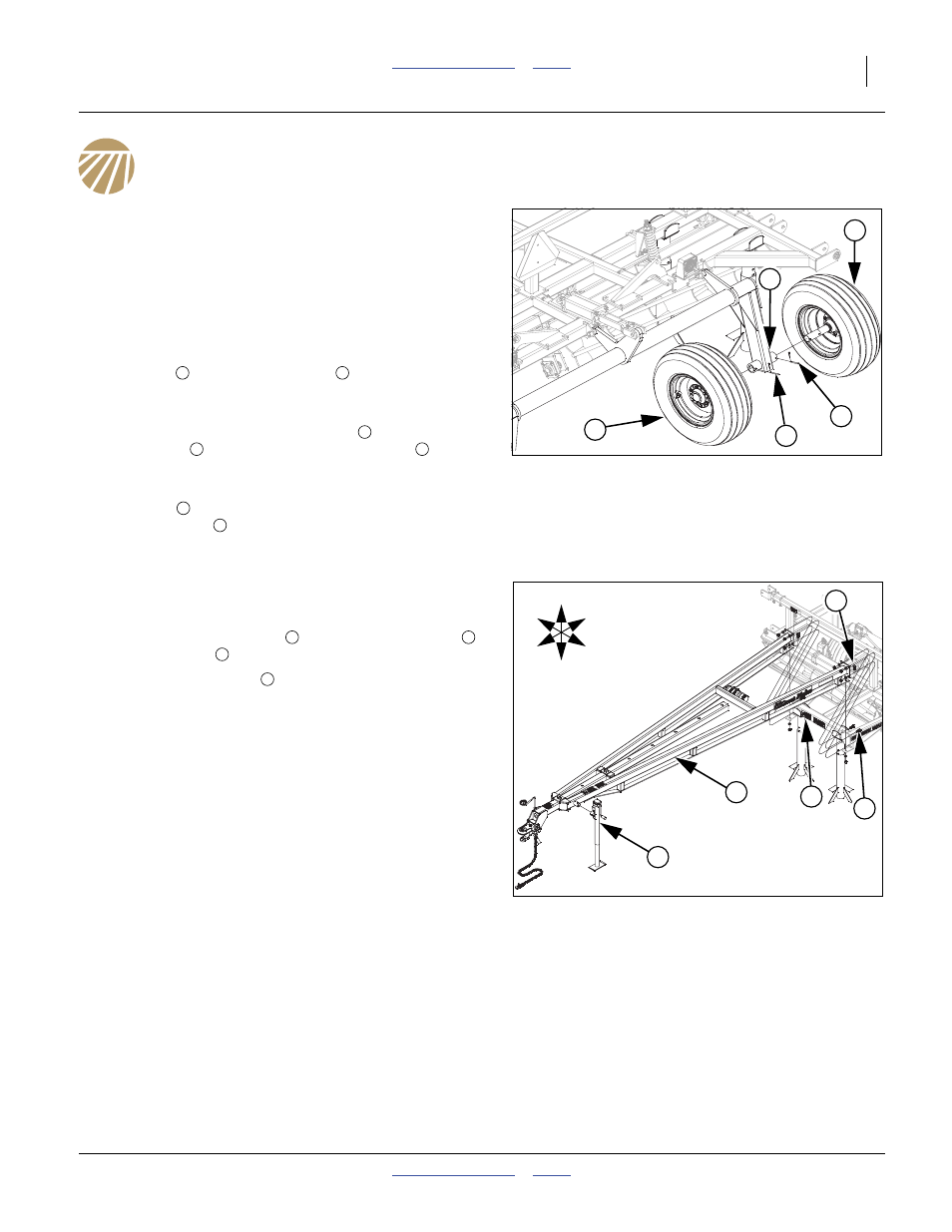
7.
Attach rear hub & wheel assemblies
into outside tube of
torque tube
, secure with 5/16x2 13/16 pin
and 1/8x1
cotter pin.
8.
If machine is equipped with the optional dual tire transport
assembly
, attach to inside tube of torque tube with 5/
16x2 13/16 pin
and 1/8x1 cotter pin.
9.
Bend cotter pins to secure.
Hitch
Refer to Figure 5
10. Attach the hitch assembly
to front of center frame
with
3/4x2 hex bolts
, 3/4 lock washers and 3/4 nuts.
11. Remove pin from jack
, swing down and re-install pin.
This will help stabilize machine during the rest of assembly.
Bolt may be tightened to specs, See “Torque Values
Chart” on page 12.
Figure 4
Hub & Wheel
42808
1
2
4
3
3
1
5
1
2
3
4
4
Figure 5
Hitch
42809
U
D
F
B
L
R
8
7
5
7
6
5
6
7
8