Radar simulator, Fig. 7 – Great Plains PM300 Assembly Instructions User Manual
Page 5
Great Plains Mfg., Inc.
5
116-008M
2/5/13
3. Disconnect the sensor from the extension harness and connect the assembly made in step
one. It can also be connected to the FDBK 1 (feedback 1) lead where the extension
harness connects to the actuator harness at the working set master.
5
6
Radar Simulator -
for application rate sensor simulation on YP planters
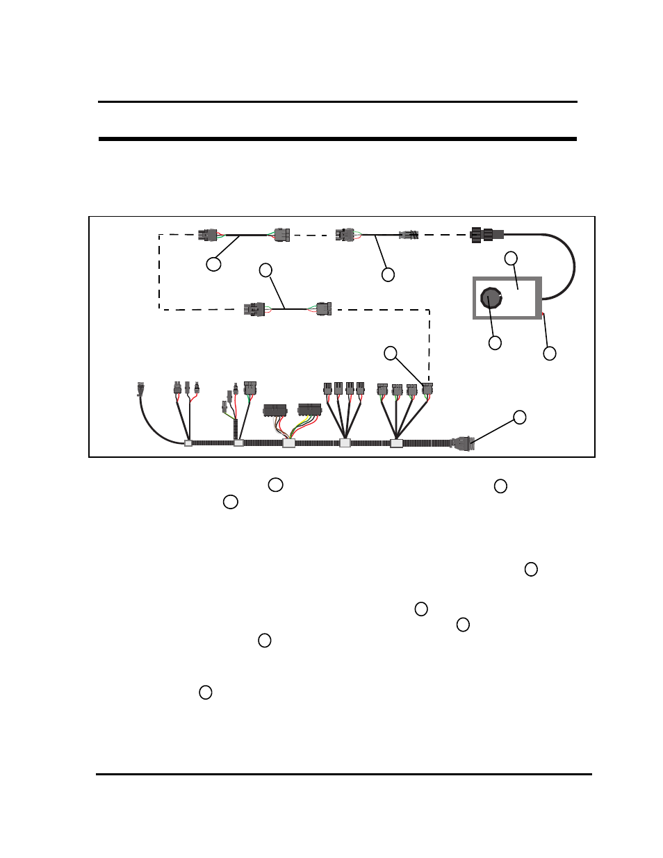
The Radar Simulator (part # AE6608) can be coupled with the Radar Sensor Adapter (part #
AE2609) and the Application Rate Sensor Adapter (part # AE2607) and connected to the
planter harness for sending a simulated application rate sensor pulse to the monitor system.
Refer to Figure 7
1. Assemble the Radar Simulator together with the Radar Sensor Adapter and the Application
Rate Sensor Adapter.
2. Locate the wiring harness coming out of the application rate sensor. On YP12 and YP16
planters, this will be found at the end of the right wing drive shaft. On all others, it will be
found on the short shaft just below the seed drive motor in the center of the implement.
Follow the lead until you find the three pin connection at the extension harness.
4. Make sure the red LED light at the top of the simulator is brightly lit. This light
indicates a good power supply coming from the harness. If the light is off or dimly lit,
make sure the monitor system is powered on and inspect the harness and connections.
5. Rotating the knob on the face of the simulator changes the pulse rate that it outputs.
A clockwise rotation will speed the pulse rate up, and a counterclockwise rotation
slows the rate down.
1
2
4
8
7
Fig. 7
Radar
Simulat
or
Po
w
er
AE6608
SN:
XXXXX
MIN
MAX
1
2
4
5
6
7
8
3
3
6. Observe the channel frequency pulse reading the channel 1 diagnostic screen. If no signal is
seen, check monitor setup. Also check the extension harness and the connection at FDBK 1