Great Plains PT8030 Parts Manual User Manual
Predelivery instructions, Manufacturing, inc
!
Read this manual entirely. When you see this symbol, the subsequent instructions and
warnings are serious - follow without exception. Your life and the lives of others depend
on it!
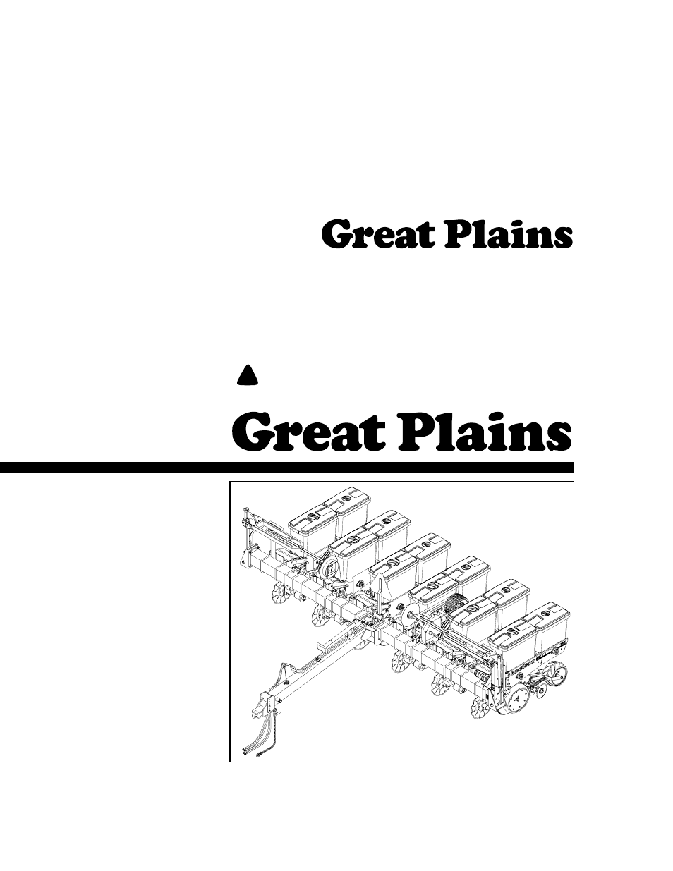
Cover illustration may show optional equipment not supplied with standard unit.
© Copyright 1999 Printed
P.O. Box 5060
●
Salina, Kansas 67402-5060
Manufacturing, Inc.
PINK
401-032Q
17931
10/14/08
Predelivery Instructions
PT6030 and PT8030
Pull-Type Planter
This manual is related to the following products:
Table of contents
Document Outline
- Introduction
- Appendix
- Important Safety Information
- Torque Values Chart for Common Bolt Sizes
- Safety Notations
- Safety Rules
- Tools Required
- Pre-Assembly Checklist
- 1. Read and understand “Important Safety Information” on page 0 before assembling.
- 2. Have at least two people on hand while assembling.
- 3. Make sure the assembly area is level and free of obstructions (preferably an open concrete area).
- 4. Have all major components.
- 5. Have all fasteners and pins shipped with the drill.
- 6. Have a copy of the parts manual on hand. If unsure of proper placement or use of any part or f...
- 7. Check that all working parts are moving freely, bolts are tight, and cotter pins are spread.
- 8. Check for proper tension and alignment on all drive chains.
- 9. Check that all safety labels and reflectors are correctly located and legible. Replace if impr...
- 10. Inflate tires to recommended pressure as listed on the Tire Inflation Chart on the “Appendix”...
- Planter Setup
- 15060
- 15 0 6 1
- 15062
- 15063
- 15072
- 5. Remove shipping stands and brackets.
- Row Unit Assembly
- 1. Disassemble row-unit springs (1) from mounting shaft (2) by removing cotter pins and washers.
- 2. Hook springs into row-unit mount (3).
- 3. Turn eye-bolts (4) so they are just below the mounting shaft (2), then turn eye-bolts back jus...
- 4. Secure springs to mounting shaft using washers and cotter pins.
- 17790
- Marker Installation
- 1. Lower the planter to the planting position. Remove the frame cap if applicable.
- 2. Block up the marker cylinders inside the frame tube so the rod ends will not contact anything ...
- 3. Extend and retract the marker cylinders several times to remove any air from the system and ch...
- 4. Assemble the first stage arms (1) onto the planter using the pivot pins that are wired into th...
- 5. Assemble second-stage arms (4) onto the end of the first-stage arms. To assemble, remove 1/2-b...
- 6. Assemble extension tubes (6) onto second-stage arms.
- 7. Start tractor and slowly extend one cylinder 6 inches. Shut tractor off. Pin the cylinder to t...
- 8. Tighten all hardware on the marker to specification. Refer to Torque Vales Chart, Appendix, pa...
- 9. Start tractor and fold marker into the storage position.
- 10. Repeat steps 7 through 9 for other marker.
- Assembly and Setup
- Marker Installation
- 16896
- 8 Row Planter
- 2. Remove a bearing (1) and retainer washer (2) from one end of the auger shaft.
- 3. Slide auger assembly (3) through hopper and fertilizer outlets. Replace bearing (1) and retain...
- 15755
- 15699
- 5. Place flow divider (1) over fertilizer outlets. Use hairpin cotter keys (2) to pin flow divide...
- 6. Attach metal straps (3) to hopper with 5/16-by-1-inch bolts (4), fender washers (5), rubber wa...
- 7. Attach tarp straps (9) to hopper lid and metal strap with 5/16-by-1 1/2-inch bolts (10), flat ...
- 15754
- 15753
- 16880
- 17931