Great Plains CF60 Predelivery Manual User Manual
Page 9
7
Section 1 Assembly
4/8/04
CF50 and CF60 Hydraulic Cross-Fold Boom 500-015Q
Great Plains Mfg., Inc.
11938
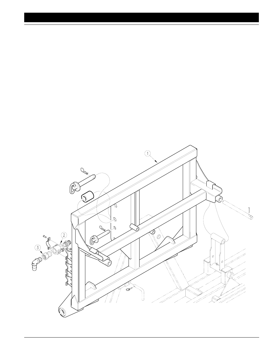
Figure 1-5
Three-Point Carrier
3.
Mount cam-lock connectors (2) onto three-point carri-
er with the six 5/16-by-3/4-inch bolts, nuts and mount-
ing brackets as shown.
4.
After the nozzles and hoses are mounted on the
boom, attach boom line hoses from three separate
boom sections to cam-lock fluid connectors (3) with
hose clamps provided. (Refer to Plumb Boom, page
10, for instructions on mounting nozzles and hoses.)
Route hose from tractor to male cam-lock fluid con-
nectors (3) which fasten into stationary female fluid
connectors mounted on three-point carrier.
5.
Route boom hoses to the tractor to ensure there is no
kinking, drooping below the tractor, or rubbing on the
tractor frame when in operation. Use the cable ties to
fasten and protect the hose.
6.
Check to see that all nuts are tightened. See the
Torque Values Chart in “Appendix” on page
Check to see that all hose clamps are tight.