Quick setup guide for intelliag model yp24 20 – Great Plains YP2425-3620 36 Row 20 Inch Quick Start User Manual
Page 2
Quick Setup Guide for IntelliAg Model YP24 20”
11001-1432C-200907
©2009 DICKEY-john Corporation
Specifi cations subject to change without notice.
STEP 6: Planter Control Channel Setup
(Controlled Hydraulic Drive)
At the Control Setup screen, press the Channel Setup button
.
Select Channel 1 and verify that the channel is set to Planter Control.
Enter desired values using Table C as reference.
After planter control setup, calibrate hydraulic valve by pressing the Valve Cal
button
.
Ensure implement is raised. With brakes locked and transmission in PARK
position, start engine.
Engage hydraulics and run engine at normal speed until hydraulic fl uid is at
operating temperature.
Verify point row clutches are turned ON.
Do NOT perform this step unless meters are installed in all locations
across planter row units or drive damage will occur.
Press the START button
. Turn the master switch to the ON position.
The valve calibration will immediately start. Keep the hydraulics engaged until
the calibration completes.
When the screen indicates calibration is complete, press the Channel Setup
button
to return to Channel 1 home screen.
Turn the master switch OFF.
To set up additional control channels (planter or fertilizer control), press the
Next Channel button
.
Press the Work Screen button
when channel confi gurations are com-
plete to return to the Main Work screen.
Once a control channel has been established as Planter Control, any new materi-
als established as Planter Control on the Material Setup screen will automatically
be added as optional materials for Planter Control channels on the Control Setup
screen.
1.
2.
3.
4.
5.
6.
7.
8.
6.
7.
8.
9.
2
STEP 7: Row Monitor Setup
At the Main Work screen, press the Row Monitor button
.
Enter desired values using Table D as reference.
Press the Work Screen button
to return to the Main Work screen.
1.
2.
3.
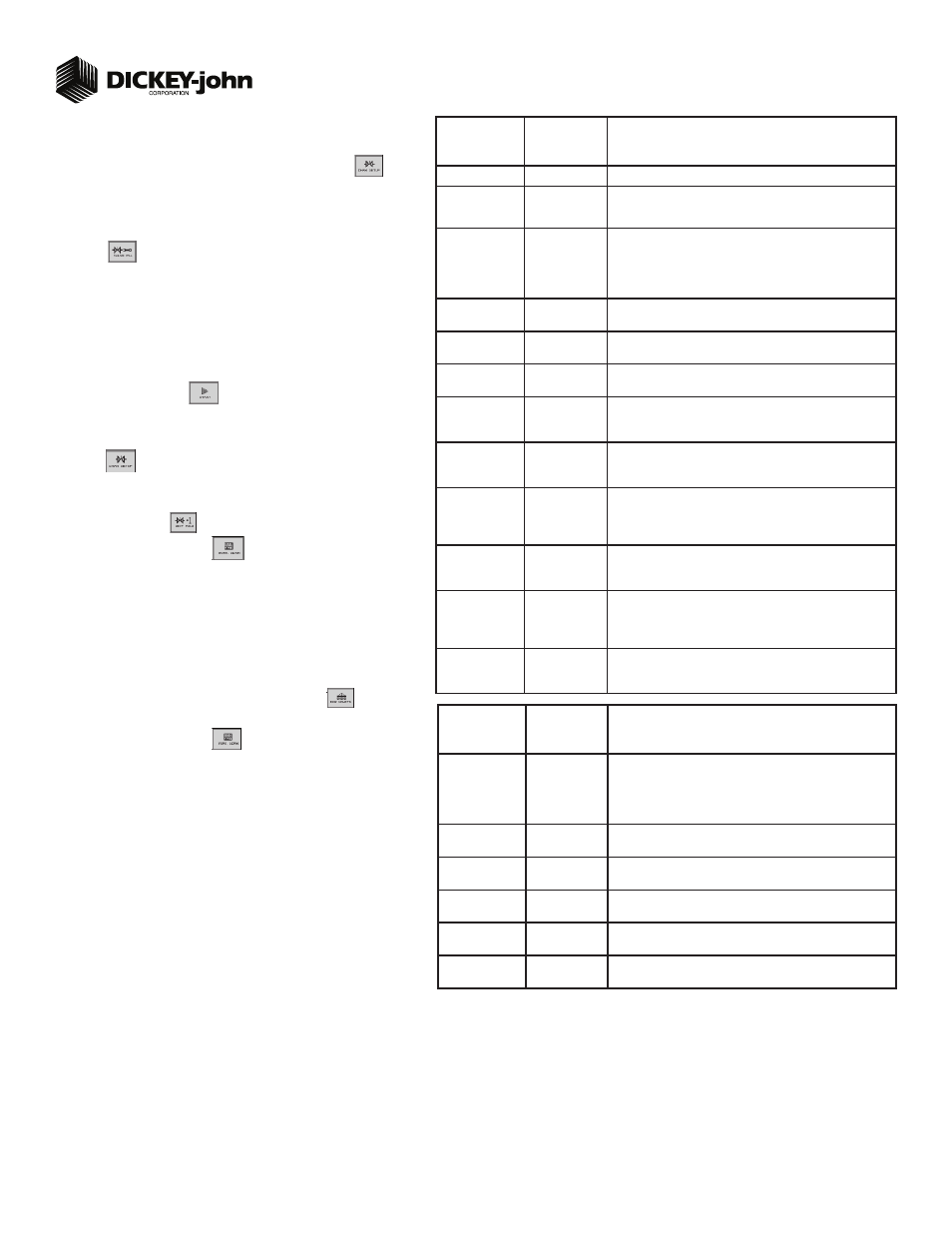
TABLE C:
Planter Control
Setup
Default Value/
Value to Enter
Instructions/Defi nitions
Type
Planter Control
Set desired Channel Type as Planter Control.
Material Name
Displays only materials that have been confi gured for the channel
type.
Control Mode
AUTO
Auto is used in normal operating conditions calculating the rate of
how the system is running. Manual mode acts as an override if
application rate sensors are inoperable allowing the use of increase/
decrease buttons to set the fl ow rate for the control. Refer to System
Confi guration section of Operator’s manual for additional information.
Drive Type
PWM
A hydraulic valve varies the oil fl ow to the motor proportioned to the
electric current supplied.
Drive Frequency
100 Hz
If not using a DICKEY-john supplied valve, see the manufacturers
specifi cations for drive frequency.
Input Filter
50
Feedback frequency fi lter for the control channel. DO NOT
CHANGE.
Gear Ratio
1.900
Specifys the actual ratio from the feedback sensor to the seed meter
shaft RPM. Number of revolutions the feedback sensor turns in rela-
tion to one revolution the seed meter turns.
Sensor Constant
360
Sensor Constant establishes the number of pulses for one revolution
of the feedback sensor. If a DICKEY-john application rate sensor is
used, the value should be set to 360.0.
# of Seed Rows
36
Entry of a specifi c number of seed rows to the control channel. Row
assignment is given a priority based on the Channel and will be
assigned sequentially thereafter. Channel 1 is always assigned to the
fi rst set of rows, Channel 2 next set of rows, and so on.
Channel Width
720
Manual entry of the channel width for rows assigned to a specifi c
channel. Width calculation can be determined by # of planter rows
assigned to the channel multipled by the row spacing.
Precharge Time
+ 0.0
Typically used during startup conditions in the fi eld, a Precharge
time is a specifi ed length of time a control channel will operate at the
defi ned precharge ground speed. Must be entered as a positive (+)
number.
Delay Time
- 0.0
Length of time before the Control Channel will start after the master
switch has been turned ON and the implement switch is in a lowered
position. Must be entered as a negative (-) number.
TABLE D:
Row Monitor
Setup
Default Value
or Value to
Enter
Instructions/Defi nitions
Material Name
See Instructions
Material Name only appears on the Row Monitor Setup screen when
all control channels are disabled and material is set for Monitor
only. This is only used for ground drive/nonhydraulic applications
to monitor population with high and low alarms. A material must be
confi gured and selected to activate alarms.
High Alarm Delay
5
Desired number of seconds that high population can be above high
alarm point before alarm will sound.
Low Alarm Delay
5
Desired number of seconds that low population can be below low
alarm point before alarm will sound.
Population Adjust
100
Enter a % to allow for seed sensor population inaccuracies to achieve
the desired population display. 100% represents true calculation.
Population Filter
50
Set fi lter value to stabilize the monitored population display. Number
can be set to 0% for no fi ltering and 99% for high level fi ltering.
Row Fail Rate
2/1 (2 seeds
every 1 second)
Set to desired number of seeds per second to trigger seed sensor
failure alarm.