Air tube disc clutches and brakes, Air system data, Psi pressure – Wichita Clutch Low Inertia (LI) High Torque Clutch User Manual
Page 9
Air Tube Disc Clutches and Brakes
52
Wichita Clutch 800-964-3262
P-1100-WC 1/12
Air System Data
PSI pressure
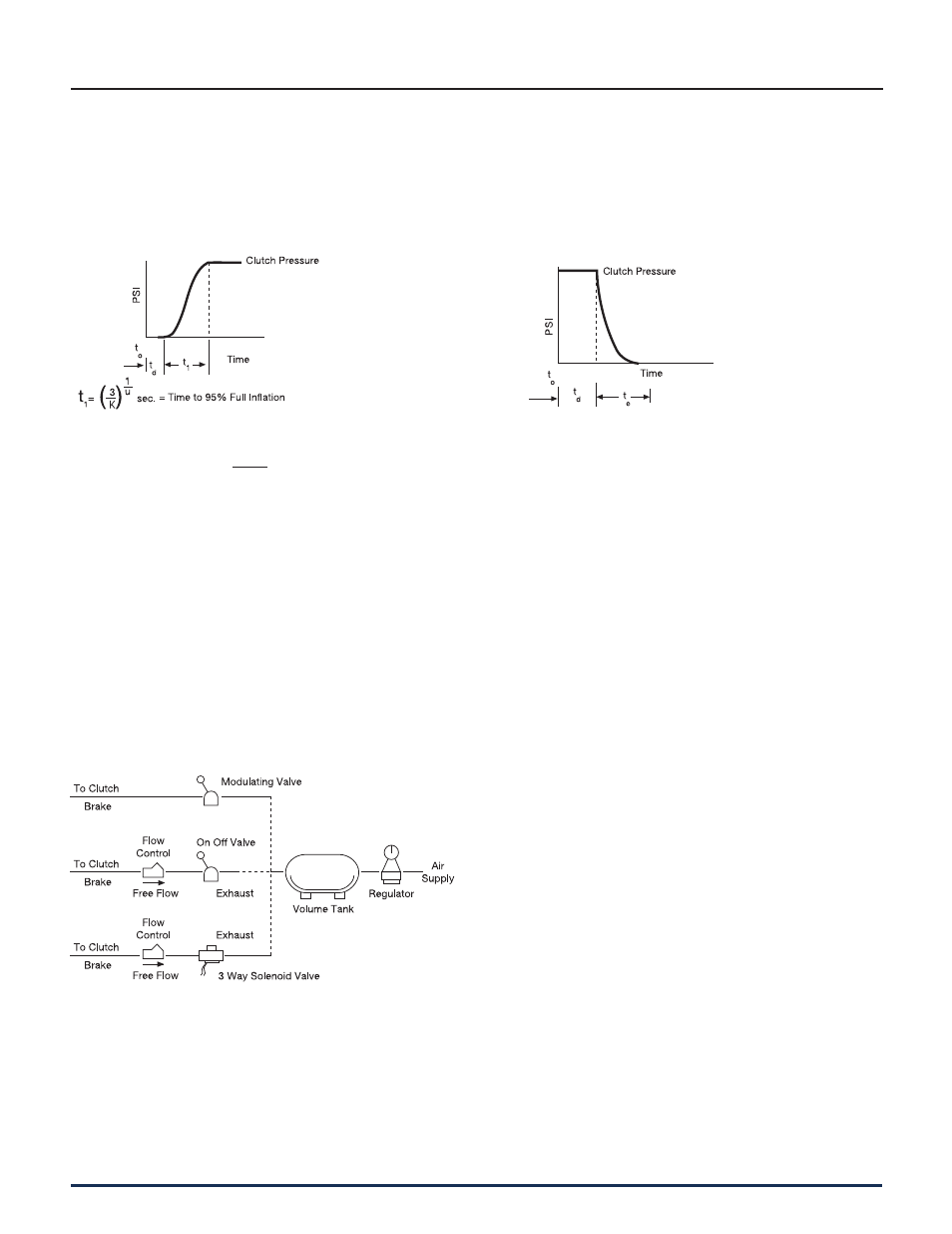
Inflation
Clutch air pressure during inflation can be
closely estimated by the following:
Clutch pressure = P
1
(
1
–
)
PSI
(inflation)
This equation is accurate from 5% up
to 95% P
1
.
P
1
= Line pressure to clutch PSI
K and U = coefficients for specific clutch and
air pressure from Spec i fi ca tion Table on
page 51.
e = Naperian base log
t
o
= Time at initiation of signal for
inflation sec.
t
d
= Time delay of air system – sec.
Exhaust
Clutch air pressure during exhaust
can be closely estimated by the fol low ing:
Clutch pressure = (P
1
) (R) (E-t)
v
PSI
(exhaust)
R, E and V = coefficients for specific clutch
and air pressure from Spec i fi ca tion
Table on page 51.
t
e
= Time to exhaust = E from Spec i fi ca tion
Table on page 51.
t = Time variable – seconds. In the
ex haust equa tion “t” cannot
exceed the value of “E” sec.
Shown are some of the air systems used
on Wichita clutches. These systems are
ac cept able for remote op er a tion where clutch
reaction time is not important. Faster clutch re -
ac tion time is ac com plished as in di cat ed in the
di a gram by lo cat ing the flow control valve, if
re quired, and the so le noid valve as close as
possible to the roto-cou pling. Where clutches
are located on long shafts, the use of quick
release valves on the clutch will fa cil i tate faster
clutch response.
1
e
Kt
u