VICI D-3-I-7890 User Manual
Page 13
9
Installation
6. Press the
sponding to the location where the PDD will be installed. For this example
we will select Back Det. The display will read:
Configured (or Unconfigured)
Ignore ready = False
[B-DET] = (Signal) (FID)
7. Press
CONFIGURE BACK DETECTOR
Remove Module < (cursor is here)
8. Press
CAUTION: Instrument power must be turned off
and back on for set point to take effect.
9. Do
not turn off the GC; instead press
CONFIGURE BACK DETECTOR
Unconfigured: < (cursor is here)
[B-Det] = (Signal) (FID)
[EPC4] Not Found
[A-Det2] Not Found
10. Press
CONFIGURE BACK DETECTOR
CPDET FID,
No Htr, No EPC <
(cursor is here)
CPDET FID, Htr, No EPC
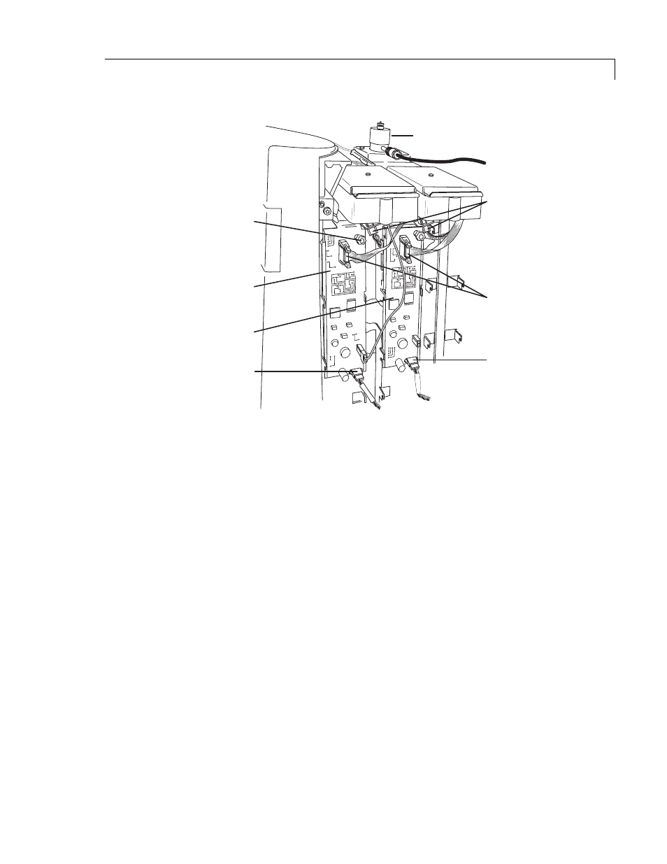
MODEL D3 IN
BACK POSITION
ELECTROMETER CABLE
CONNECTIONS
HEATER CABLE
CONNECTIONS
FRONT OF 7890
FID LOGIC BOARD
FOR BACK POSITION
FID LOGIC BOARD
FOR FRONT POSITION
THUMBSCREW
B-DET CABLE
CONNECTION
F-DET CABLE
CONNECTION
F-DET
B-DET
Figure 5: 7890 FID logic board