Gas connections, Horizontal mounting – VICI D-2-I User Manual
Page 18
14
Horizontal Mounting
Some older GCs have access to the column oven through the side of the
GC. This does not present a problem as far as operation of the PDD is
concerned. Drill a hole at the appropriate location, orient the detector for
convenient connection, and mark the position of the mounting holes. Drill
the mounting holes and secure the detector to the side of the GC with four
sheet metal screws (not supplied).
Gas Connections
Remember these three points discussed earlier: (1) all surfaces that contact
the gas stream must be glass or stainless steel; (2) do not use copper
tubing or brass fittings; and (3) all tubes must be thoroughly cleaned and
baked before use. The installation instructions below assume that the
detector discharge will be supplied from a nearby cylinder of helium of the
proper purity. If your installation is different, you may need to modify the
instructions appropriately. A number of Valco fittings have been supplied
in the fittings kit to handle different situations.
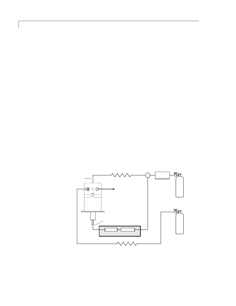
Figure 3 illustrates gas connections for a typical detector system using a
PD-D2 detector in the ECD mode. For HID and PID modes, disconnect the
restrictor TGA-R-04F30P, cap the line, and plug the dopant inlet.
Figure 4
illustrates gas connections for the PD-D2-IS detector system. Since the
distance from the helium supply to the GC varies from installation to
installation, we do not supply tubing to go from that point to the GC.
Installation
GAS CHROMATOGRAPH
COLUMN
INJECTOR
TEE
(ZT1)
HELIUM
PURIFIER
DISCHARGE GAS
(99.999% He)
TGA-R-04F30P
RESTRICTOR
TGA-R-30F60P
RESTRICTOR
(30 mL/min minimum)
VENT
COLUMN INLET
DISCHARGE GAS
INLET
DOPANT GAS
(3% Xe in He)
DOPANT
VENT
Figure 3: Gas connections for a PD-D2 in the ECD mode