Control layout – SCHOEPS KFM 360 User Manual
Page 11
11
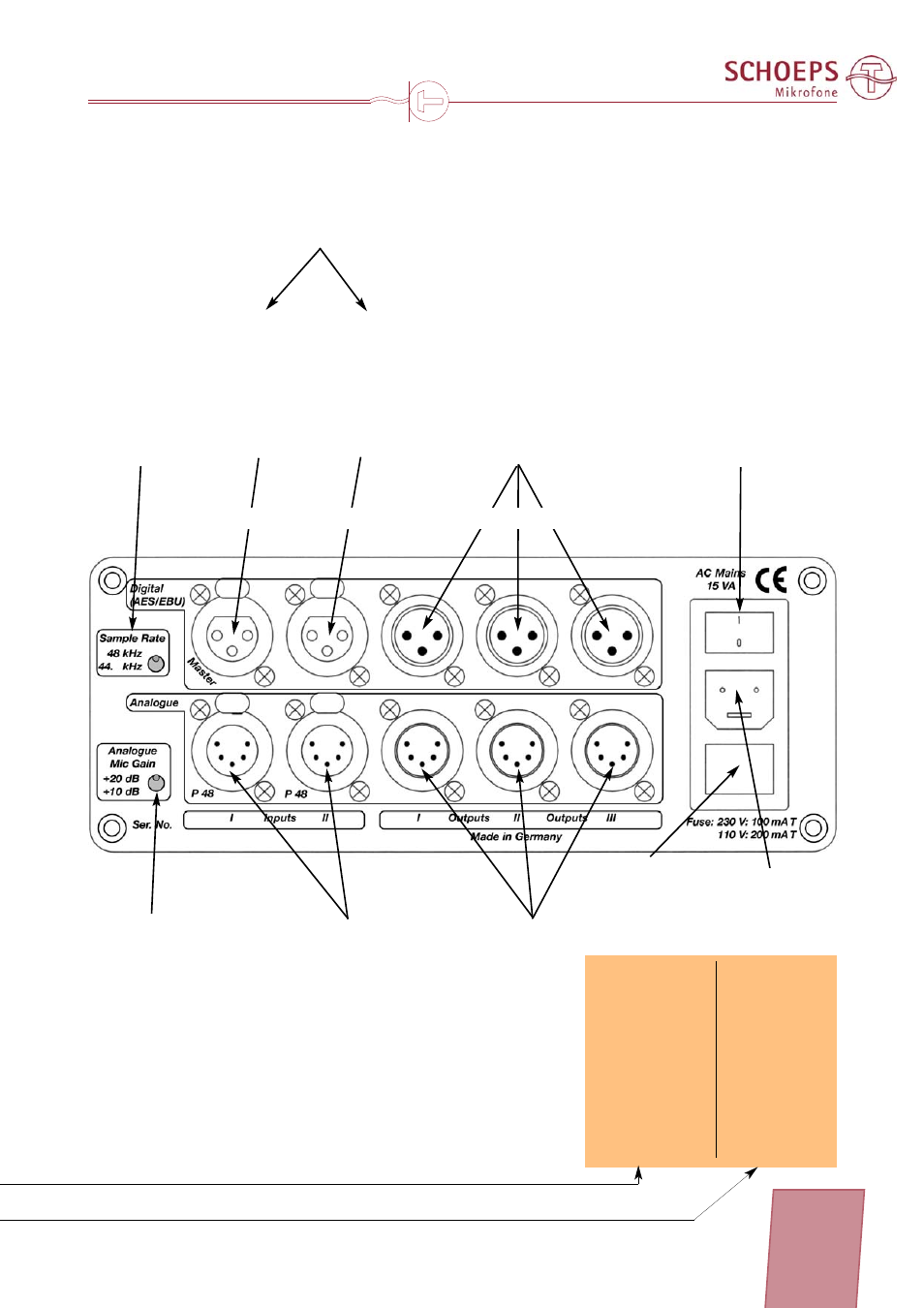
Control layout
Power on/off switch
Power cord
socket
Safety fuse /
AC voltage selector
Analog microphone inputs
with 48 V phantom powering
(muted if digital master and
slave inputs are connected)
Input I:
channel 1: left omni
channel 2: right omni
Input II:
channel 1: left figure-8
channel 2: right figure-8
Digital
outputs
Gain selector
for analog
inputs
Sampling rate
selector (internal
clock for A/D con-
verters)
Master*
(AES/EBU)
for synchro-
nizing the
internal A/D
converters
Slave
(AES/EBU)
switches over
to the digital
inputs
Analog
outputs:
SURR mode (B): REC mode (A):
Output I:
channel 1: left front
left omni
channel 2:
right front
right omni
Output II:
channel 1:
center
left figure-8
channel 2:
bass (LFE)
right figure-8
Output III:
channel 1:
left surround
left monitor
channel 2:
right surround
right monitor
Rear panel
Digital inputs
(recorder playback)
Channel assignment just as with the analog in/outputs
*The reason for having the master clock func-
tion and the slave input on two separate
sockets is that this allows the converters to
be slaved to an external source while the ana-
log inputs are being used (see example on
page 17).