2 tightening torques, 3 flow rates, 4 minimum differential pressures – Richter BCV/F (ASME) Series Check Valves User Manual
Page 4: Tightening torques, Flow rates, Minimum differential pressures, Series cv/f, cvv/f, bc/f, bcv/f
Series CV/F, CVV/F, BC/F, BCV/F
Page 4
9550-050-en
Revision 10
TM 8462
Edition 02/2012
Body identification:
The following are visible on the body according to DIN
EN 19 and AD 2000 A4:
Nominal size
Rated pressure
Body material
Manufacturer's identification
Melt number/Foundry identification
Cast date
Arrow for direction of flow
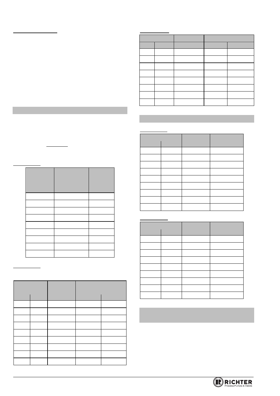
1.2 Tightening torques
All screws greased, tighten in diametrically
opposite sequence!
The tightening torques for pipe screws and body
screws mentioned must not be exceeded. For an
exception, see Section 8, Flange connection valve /
pipe is leaking.
The following tightening torques are recommended.
Pipe screws, flanges to ISO/DIN
Flange
Nominal
size
Screws
Tightenin
g torque
moment
[mm]
[ISO/DIN]
[Nm]
15
4 x M 12
6
20
4 x M 12
8
25
4 x M 12
10
40
4 x M 16
20
50
4 x M 16
26
65
4 x M 16
40
80
8 x M 16
25
100
8 x M 16
35
150
8 x M 20
65
Pipe screws, flanges to ISO/DIN drilled to ASME
Class 150 or flanges ASME B 16.5 Class 150, raised
face
Flange
Nominal size
Screws
Tightening torque
[mm]
[inch]
[ASME]
[in-lbs]
[Nm]
15
½
4 x ½“
45
5
20
¾
4 x ½“
55
6
25
1
4 x ½“
70
8
40
1½
4 x ½“
135
15
50
2
4 x O“
220
25
65
2½
4 x O“
265
30
80
3
4 x O“
400
45
100
4
8 x O“
310
35
150
6
8 x ¾“
710
80
Body screws
Nominal size
Screws
Tightening torque
[mm]
[inch]
[ISO/DIN]
[in-lbs]
[Nm]
15
½“
4 x M 12
220
25
20
¾“
4 x M 12
220
25
25
1“
4 x M 12
220
25
40
1½“
4 x M 16
442
50
50
2“
4 x M 16
442
50
65
3“
8 x M 16
442
50
80
4“
8 x M 16
442
50
100
6“
8 x M 16
442
50
1.3 Flow rates
CV/F, CVV/F
Nominal size
Cv
Kv 100
[mm]
[m3/h]
15
½“
7.3
8.5
20
¾“
13.7
16
25
1“
23.2
27
40
1½“
83.4
97
50
2“
105
122
65
2½“
49
57
80
3“
258
300
100
4“
353
410
150
6“
310
330
BC/F, BCV/F
Nominal size
Cv
Kv 100
[mm]
[m3/h]
15
½“
7.3
8.5
20
¾“
13.7
16
25
1“
19
22
40
1½“
54
61
50
2“
79
92
65
1½“
--
--
80
3“
172
200
100
4“
310
360
150
6“
310
330
1.4 Minimum differential
pressures
Installation position
horizontal
vertical
CV/F
1 bar
20 mbar
CVV/F
0,5 bar
10 mbar
BC/F
15 psi
0,30 psi
BCV/F
7 psi
0.12 psi
If the CVV/F/BCV/F is installed as ventilation valve, it
will close from a density of 1 kg/dm
3
upwards.