Revel M106 User Manual
Page 5
5
Revel Performa3 M106/M105 Bookshelf Loudspeaker
Owner’s Manual
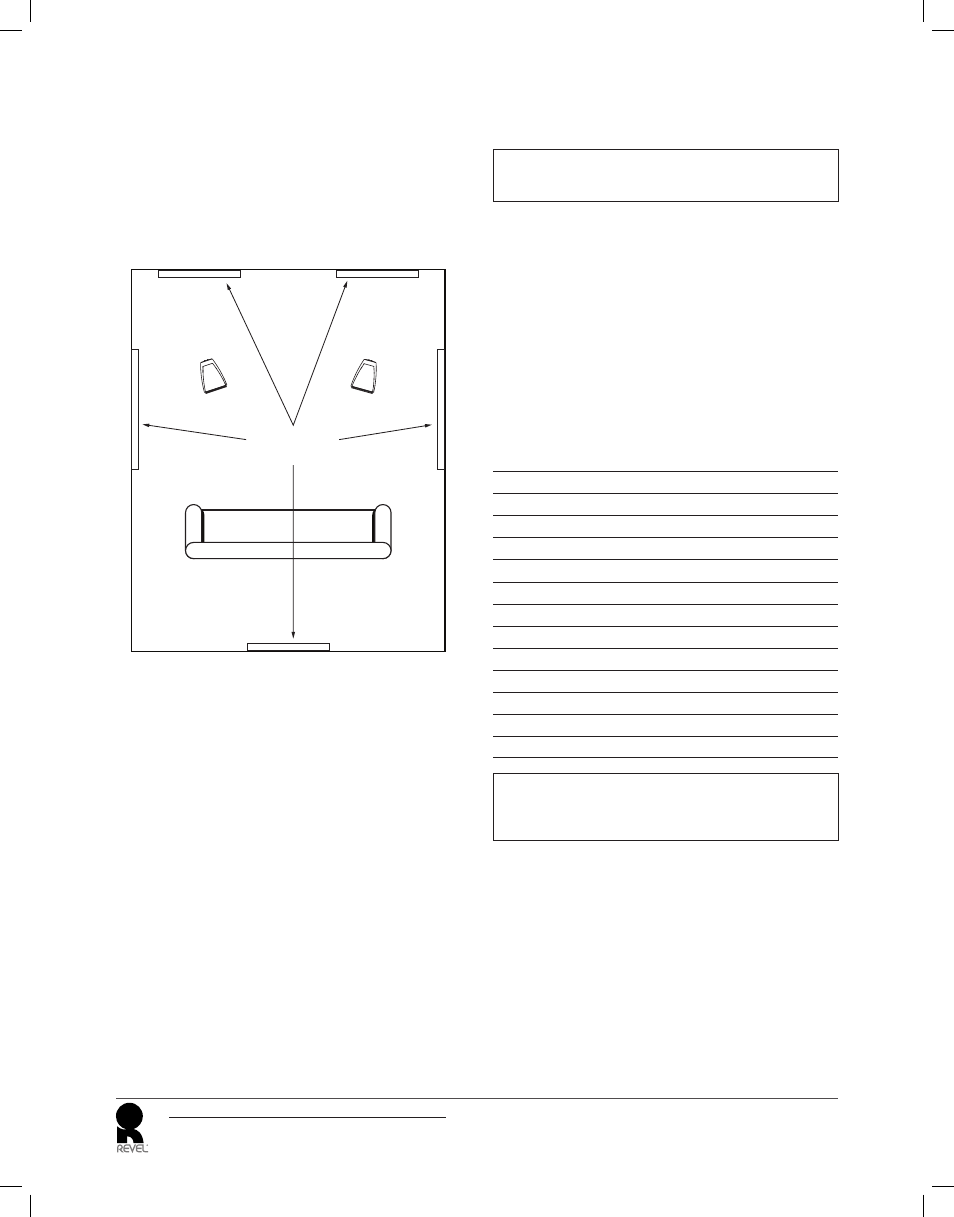
aCOUStiC treatment materiaLS
The M106 and M105 feature high-order fi lters that optimize the
loudspeakers’ on-axis and off-axis response, minimizing sonic
degradations that occur in overly “live” rooms (those with surfaces that
are acoustically refl ective). Placing minimal acoustic treatment materials
at the room’s primary refl ection points will reduce these distortions even
further. Ideally, acoustic absorbers should be placed at the fi rst refl ection
points on the front and side walls and either acoustic absorbers or
diffusers should be placed at the fi rst refl ection points on the rear wall.
Front Wall
Acoustic
Treatment
Materials
Right
M106/M105
Left
M106/M105
Because the listener’s eyes and ears are on the same plane, the “mirror
method” is an accurate determinant of critical refl ection points. This
method can be used to determine refl ection points for side walls, rear
walls, front walls, and even the ceiling. Applying acoustic treatment
materials to the side walls is most important, followed by the ceiling,
front wall and rear wall.
To determine refl ection points using the mirror method:
1. Once the loudspeakers have been placed, sit in the primary
listening position and ask another person to slide a mirror along
the listening room walls.
2. Note the locations at which you can see either loudspeaker in the
mirror from the primary listening position. Be sure to look for both
loudspeakers in the refl ection on each room boundary. These are
refl ection points that require acoustic treatment materials.
If acoustic treatment materials are not available, hanging a rug over
the refl ection points will help reduce sonic degradation in overly
“live” rooms. Carpeting the fl oor area between the loudspeakers and
the primary listening position and placing irregular surfaces such as
bookcases at the fi rst refl ection points will also help minimize strong
refl ections.
maKinG COnneCtiOnS
CAUTION: Never make or break connections unless all
system components are powered off.
OBSerVe PrOPer POLarity
Connect the amplifi er’s positive (+) terminal to the positive (+) terminal
on the corresponding speaker; connect the amplifi er’s negative (–)
terminal to the negative (–) terminal on the corresponding speaker. Do
not reverse polarities (that is, do not connect + to –, or – to +) when
making connections. Doing so will cause poor stereo imaging and
diminished bass response.
SPeaKer CaBLe
Use high-quality loudspeaker cable with a maximum total loop
resistance of 0.07 ohms or less for each wire run. Refer to the table
below to determine the appropriate wire gauge for your installation.
minimUm Wire GaUGe
Maximum Wire
Length (Feet)
Maximum Wire
Length (Meters)
Minimum Wire
Gauge (AWG)
< 87
< 27
6
< 69
< 21
7
< 58
< 18
8
< 43
< 13
9
< 34
< 10
10
< 27
< 8
11
< 22
< 7
12
< 17
< 5
13
< 14
< 4
14
< 11
< 3.5
15
< 9
< 3
16
< 7
< 2
17
< 5
< 1.5
18
NOTE: High loop resistances that exceed 0.07 ohms (for each
wire run) will cause the loudspeaker’s fi lter network to be mis-
terminated, resulting in considerable degradation of sound quality.