Bezeichnungen, Aufbau & anschlüsse, Designation – Reloop RP-6000 MK6B User Manual
Page 3: Setting up & connections, Désignations, Assemblage & connexions
5
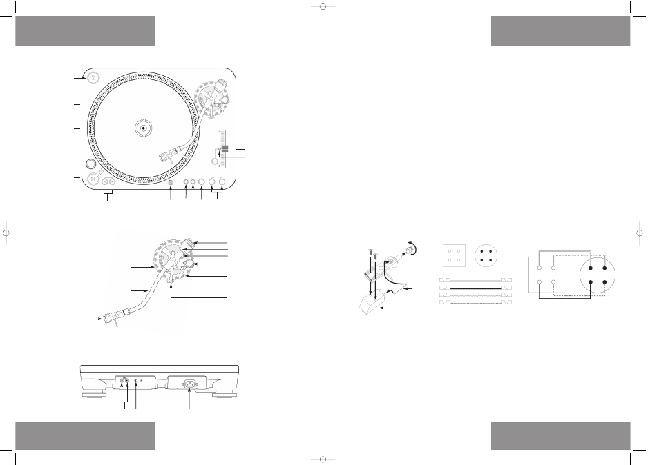
Bezeichnungen
1.
Plattenteller
2.
Nabe
3.
EIN/AUS Schalter auf Plattentellerbeleuchtung
4.
START/STOP Taster
5.
33/45/78 Umschalter
6.
Nadelbeleuchtung und Buchse für Nadelbeleuchtung
7.
Regler für Start- und Stoppgeschwindigkeit
8.
Regler für Startdrehmoment
9.
Rückwärtslauf-Schalter
10. Pitchbereich-Wahlschalter
11.
Quarz-Lock Schalter
12. Quarz-Lock LED
13. Pitchfader
14. Headshell
15. Tonarm
16. Tonarmkranz
17. Tonarmstütze
18. Tonarmlift
19. Anti-Skating Rad
20. Tonarmkranz-Arretierung
21. Gegengewichtsskala
22. Gegengewicht
23. Audio Ausgangskabel (Cinch)
24. Phono/Line Switch
25. Anschlussbuchse für das Netzkabel
Aufbau & Anschlüsse
1.
Befestigen Sie den Plattenteller -1- auf dem Motor. Legen Sie
dazu den Plattenteller über die Nabe -2-.
2.
Legen Sie das mitgelieferte Slipmat über die Nabe -2- auf den
Plattenteller.
3.
Stecken Sie das Gegengewicht -22- auf den Tonarm -15-.
HINWEIS!
Die Gegengewichtsskala -21- muss dabei auf der dem DJ
zugewandten Seite sein.
4.
Schrauben Sie das Headshell -14- in den Tonarm -15- ein,
nachdem Sie Ihr Tonabnehmersystem am Headshell wie folgt
montiert haben:
a) Verbinden Sie die Anschlussdrähte des Headshells mit den
Anschlüssen des Tonabnehmersystems und beachten Sie die
Übereinstimmung der Drähtebelegung:
Farbe:
Kanal und Polung
I Weiß (L+)
Links, Plus-Pol
II Blau (L-)
Links, Minus-Pol
III Rot (R+)
Rechts, Plus-Pol
IV Grün (R-)
Rechts, Minus-Pol
b) Befestigen Sie das Tonabnehmersystem mit den ihm beili-
genden Befestigungsschrauben.
HINWEIS!
Wenn Sie anstatt eines Headshell-Tonabnehmersystems ein
direktmontierbares SME-Tonabnehmersystem verwenden,
so schrauben Sie dieses direkt in den Tonarm -15- ein; das
Headshell findet dann keine Verwendung.
5. Stecken Sie die Nadelbeleuchtung in die dafür vorgesehne
Buchse -6-.
6.
Verbinden Sie die Audio Ausgangskabel -23- mit den Audio
Eingängen Ihres Mischpults.
7.
Verbinden Sie das Netzkabel mit der Anschlussbuchse -25- und
mit einer Steckdose.
Designation
1.
Turntable
2.
Hub
3.
ON/OFF switch turntable illumination
4.
START/STOP button
5.
33/45/78 selector
6.
Stylus light and jack for stylus light
7.
Start / Stop pitch control
8.
Starting Torque control
9.
Reverse switch
10. Pitch selector
11.
Quartz lock switch
12. Quartz lock LED
13. Pitch fader
14. Headshell
15. Pick-up arm
16. Pick-up arm collar
17. Pick-up rest
18. Pick-up lift
19. Anti-skating wheel
20. Pick-up arm collar lock
21. Balancing weight scale
22. Balancing weight
23. Audio output cable (RCA)
24. Phono/Line Switch
25. Connecting socket for mains line
Setting up & connections
1.
Attach the turntable -1- to the motor. For this place the
turntable above the hub -2-.
2.
Place the supplied slipmat above the hub -2- onto the turntable.
3.
Place the balancing weight -22- onto the pick-up arm -15-.
NOTE!
The balancing weight scale -21- must face toward the DJ.
4.
Screw the headshell -14- into the pick-up arm -15- after having
mounted your pick-up system as followed to the headshell:
a) Connect the connecting wires of the headshell with the
connections of the pick-up system and observe the
correspondence with the following wiring instructions:
Colour:
Channel and polarity
I White (L+)
left, plus terminal
II Blue (L-)
left, minus terminal
III Red (R+)
right, plus terminal
IV Green (R-)
right, minus terminal
b) Attach the pick-up system with the enclosed fastening
screws.
NOTE!
If using a direct-mount SME pick-up system instead of a
headshell pick-up system simply screw this directly into
the pick-up arm -15-; in such a case, the headshell is not to
be used.
5.
Insert the stylus light into the respective jack -6-.
6.
Connect the audio output cable -23- with the audio input of
your mixer.
7.
Connect the mains line with connecting socket -25- and an
outlet.
Désignations
1.
Table de lecture
2.
Broche centrale
3.
Interrupteur de l'éclairage de la table de lecture
4.
Touches START/STOP
5.
Commutateur 33/45/78
6.
Lumière cible et connecteur de lumière cible
7.
Regleur pour vitesse de démarrage et d'arrêt
8.
Regleur pour couple de démarrage
9.
Touche de marche inversée
10. Sélecteur Pitch
11.
Touche Quartz-Lock
12. DEL Quartz Lock
13. Curseur Pitch
14. Cellule
15. Bras de lecture
16. Molette du bras de lecture
17. Support de bras de lecture
18. Lève-bras
19. Molette anti-dérapage
20. Blocage de la molette du bras de lecture
21. Graduation contre-poids
22. Contre-poids
23. Câble de sortie audio (coaxial)
24. Phono/Line Switch
25. Connecteur pour le cordon secteur
Assemblage & connexions
1.
Fixez la table de lecture -1- au moteur. Insérez la table de
lecture dans la broche centrale -2-.
2.
Placez la feutrine sur la table de lecture en l'insérant dans la
broche centrale -2-.
3.
Fixez le contre-poids -22- sur le bras de lecture -15-.
REMARQUE
La graduation de contre-poids -21- doit être dirigée vers le DJ.
4.
Vissez la cellule -14- au bras de lecture -15- après avoir monté
votre tête de lecture sur la cellule en procédant comme suit :
a) Branchez les fils de connexion de la cellule aux connecteur
de la tête de lecture en respectant les affectations indiquées
dans la table ci-dessous :
Couleur
Canal et polarité
I Blanc (L+)
Gauche, positif
II Bleu (L-)
Gauche, négatif
III Rouge (R+)
Droite, positif
IV Vert (R-)
Droite, négatif
b) Fixez la tête de lecture avec les vis fournies.
REMARQUE
Si au lieu d'une tête de lecture avec cellule, vous utilisez
une tête de lecture SME à montage direct, vissez-la
directement au bras de lecture -15- ; la cellule est alors
superflue.
5.
Enfichez la lumière cible dans le connecteur prévu à cet effet -6-.
6.
Branchez le câble de sortie audio -23- sur l'entrée audio de votre
console de mixage.
7.
Branchez le cordon secteur sur le connecteur d'alimentation -25-
et une prise secteur.
4
1
2
3
4
5
13
11
4
6
7
8
9
10
12
14
22
19
18
17
15
16
21
20
24
23
25
Tonabnehmer /
Pick-up System/
Tête de lecture
Headshell
I
II
III
IV
I
III
II
IV
I
III
II
IV
I
III
II
IV
Ihr Tonabnehmer /
Your Pick-up System /
votre tête de lecture
x4
Bedienoberfläche
Tonarm
Rückseite
Controls
Pick-up arm
Rear Panel
Panneau de commande
Bras de lecture
Face arrière
instrManual_RP6000MK6LTD 01.03.2007 14:51 Uhr Seite 04