Oil-fired – Bock Water heaters Commercial Oil-Fired Water Heaters User Manual
Page 2
Oil-Fired
www.bockwaterheaters.com
110 South Dickinson Street , Madison, Wisconsin 53703
Toll Free 800.794.2491
•
Phone 608.257.2225
●
Fax 608.257.5304
80014-C Rev 2/08
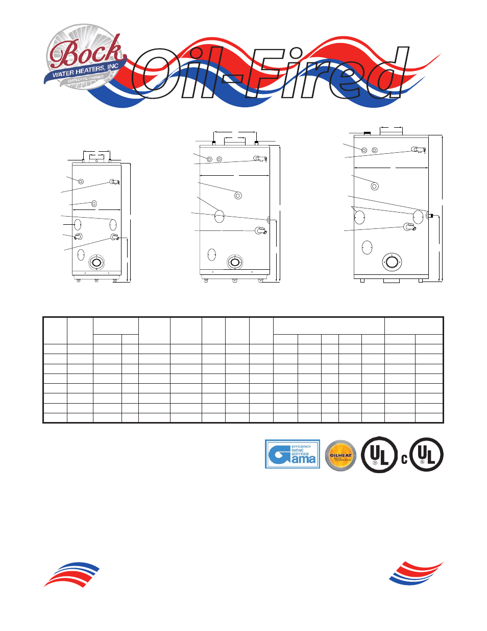
*Nipple not included
**Optional setting, contact factory
***Weight does not include burner and controls
T&P Valve: Factory Installed
Drain Valve: Factory Installed Brass Valve
Standard Voltage (all): 120V, 60 Hz, 1P
Pressures (all): Working Pressure, 150 psi; Testing Pressure, 300 psi
ASHRAE: All Bock Products Meet or Exceed Current ASHRAE Standards.
Warning: Do not install on combustible flooring. Installation should be in accordance with all national and/or local codes. In the absence of local
codes, refer to NFPA 31 or ANSI Z.21.10.1.
Caution: The recommended maximum hot water termperature setting for normal residential use is 120°F. Bock recommends a tempering valve or
anti-scald valve be installed and used according to the manufacturer’s directions to prevent scalding.
(on selected models)
71E
72E, 73E, 120E,
541E
190E, 241E, 361E
Model Storage
(gal)
Rated Input
Recovery
@ ∆ 90°F
(GPH)
Max. Temp
Setting
(°F)
Inlet
Pipe
Dia.
Outlet
Pipe
Dia.
Return
Pipe
Dia.
Dimensions
Shipping Weight
(lbs)***
BTH/HR GPH
A
B
C
D
E
Standard
ASME
71E
68
173,000
1.25
177
160**
1”
1 1/2”*
1 1/2”
66”
26”
6”
13 1/2”
22”
438
N/A
72E
67
199,000
1.50
212
160**
1”
1 1/2”*
1 1/2”
58”
28”
8”
16”
N/A
503
N/A
73E
67
242,000
1.75
258
180
1”
1 1/2”*
1 1/2”
58”
28”
8”
16”
N/A
503
N/A
120E
113
155,000
1.10
163
180
1”
2”*
2”
67”
31 1/2”
6”
19”
22”
709
N/A
190E
113
190,000
1.35
199
180
1”
2”*
2”
67”
31 1/2”
6”
19”
22”
709
N/A
241E
109
277,000
2.00
286
180
1”
2”*
2”*
67”
31 1/2”
8”
19”
22”
856
912
361E
91
415,000
3.00
443
180
1”
2”*
2”*
67”
31 1/2”
9”
23”
26”
1014
1050
541E
83
623000
4.5
648
180
2”
2”*
2”*
66”
34”
10”
N/A
30 1/2”
1232
1258
Outlet
Auxiliary
Outlet:
32EC/BCS,
71EC,
51EC/BCS
Inlet
T&P
Relief
Valve
D
C
B
E
A
Drain
Valve/
Return:
32E,
50ES, 51E
Aquastat
Connection
Drain
Valve/
Return:
71E
Hand-Hole:
50ES
Hand-Hole:
71E
Outlet
Auxiliary
Outlet
Inlet
T&P
Relief
Valve
D
C
B
E
A
Drain
Valve/
Return
Aquastat
Connection
Hand-Hole
Return:
120E,
190E,
241E,
361E
Outlet
High Limit
Inlet/
Return
T&P
Relief
Valve
C
B
E
A
Drain
Valve
Aquastat
Connection
Hand-Hole