Sphx instruction sheet – Harrington Signal SPHX-DVSMR User Manual
Page 3
- 3 -
256883
SPHX Instruction Sheet
c.
Carefully reinstall housing cover using eight 5/16-18 x 1-
3/4" hex head bolts, lockwashers and hex nuts that were previously
removed. Verify that all housing and mounting bolts have been securely
tightened.
WARNING
Property damage, serious injury, or death could occur if the
housing is not closed properly. To reduce possibility of
explosion, housing cover must be kept tight (all eight bolts fully
tightened) while circuits are energized.
D.
TESTING/OPERATING.
WARNING
Under certain conditions these devices are capable of pro-
ducing sounds loud enough to
cause hearing damage.
Adequate hearing protection should be worn if standing within
close proximity to device while testing. Recommendations in
the OSHA Sound Level Standard (29 CFR 1910) should not
be exceeded.
1.
After installation is complete, be sure to test the system to
verify that each speaker operates satisfactorily. If it is found that the unit
is too loud for its location, a lower wattage tap may be selected. Carefully
remove the housing cover and move the positive (+) lead to a lower
wattage tap (see Figure 3). Reinstall the housing cover and retest.
WARNING
Property damage, serious injury, or death could occur if the
housing is not closed properly. To reduce possibility of
explosion, housing cover must be kept tight (all eight bolts fully
tightened) while circuits are energized.
2.
After completion of initial system test, establish a program for
periodic testing of this device. Refer to NFPA 72, local Fire Codes and
the authority having jurisdiction for this information.
3.
Provide a copy of these instructions for the Safety Engineer,
system operator(s) and maintenance personnel.
SAFETY MESSAGE TO OPERATORS
Even if your warning system is operating properly, it may not
be completely effective. People may not hear or heed your
warning signal. You must recognize this fact and ensure that
your warning signal achieves its intended effect through
proper test/training sequences within your specific
application(s).
E.
MAINTENANCE.
SAFETY MESSAGE
T O
MAINTENANCE PERSONNEL
Figure 2. Typical Installation Wiring.
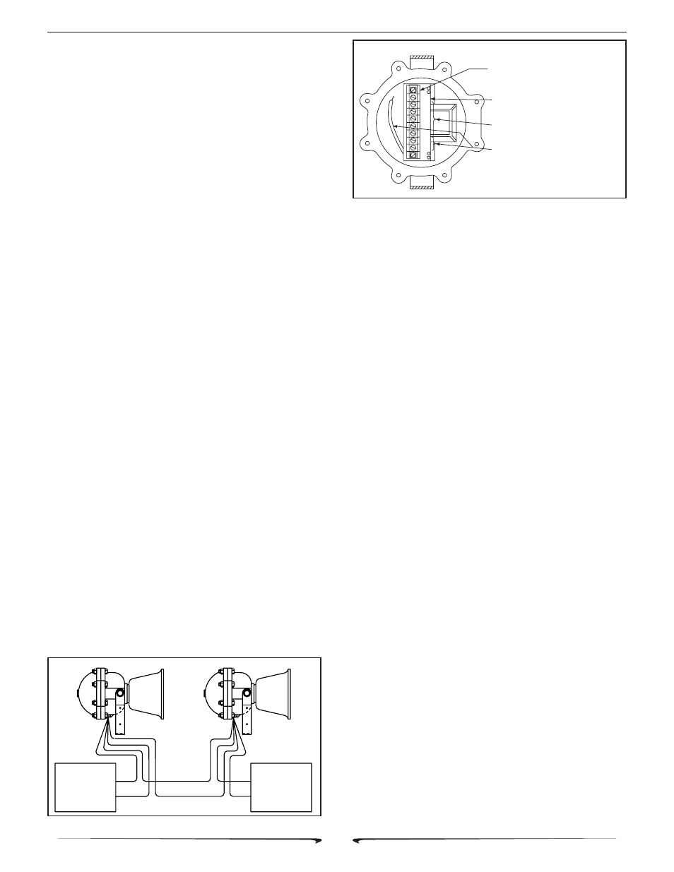
Figure 3. Internal Multi-tap Wiring Set-up.
Failure to follow all safety precautions and instructions may result
in property damage, serious injury, or death to you or others.
•
Read and understand all instructions before performing
maintenance on this unit.
•
Do not perform maintenance on this unit when circuits are
energized.
•
Periodic checks should be made to ensure that effective-
ness of this device has not been reduced because
speaker has become clogged with a foreign substance
or because objects have been placed in front of the
speaker.
•
Any maintenance to this unit MUST be performed by a
trained electrician in accordance with NEC guidelines
and local codes.
•
Never alter this unit in any manner. Safety in hazardous
locations may be jeopardized if additional openings or
alterations are made to this device.
•
The nameplates, which contain cautionary or other
information of importance to maintenance personnel,
should not be obscured if exterior of device is painted.
WARNING
Effectiveness of explosion-proof enclosure must be maintained. Use
caution to avoid damaging machined surfaces.
1.
Periodically check this device to verify that there are no
foreign substances in, or in front of, the speaker which will reduce its
effectiveness.
2.
Testing should be periodically performed. Refer to NFPA 72,
local Fire Codes and the authority having jurisdiction for information.
3.
In the event a volume adjustment or other repair is required,
be sure to refer to the Safety Message For Maintenance Personnel
before proceeding.
WARNING
Unauthorized repair/servicing of the unit may result in degradation of
performance and/or property damage, serious injury, or death to you
or others. If a malfunctioning unit is encountered, do not attempt any field
repair/retrofit of parts.
F.
SERVICE.
This product is covered by a 5 year limited warranty. See CPG
terms and conditions for details.
The factory will service your equipment or provide technical
NOTE: LETTERS APPEAR ON THIS SIDE OF
TERMINAL STRIP. SHOWN HERE ON MOUNT
-ING BRACKET FOR REFERENCE ONLY.
FIELD COMMON (-) LEADS TO COMMON
TERMINAL
FIELD POSITIVE (+) LEADS TO 1 OF 5
WATTAGE TERMINALS.
SPEAKER INTERNAL GREEN OR RED LEAD
TO BE CONNECTED TO 25V OR 70V
TERMINAL (DEPENDENT UPON EXTERNAL
SIGNAL SOURCE VOLTAGE).
290A2627-03
COM
.5W
1W
2W
7W
15W
25W
70W
25 OR 75 VRMS
SPEAKER
SIGNAL SOURCE
SPEAKER
MODEL
SPHX
290A2627-02
BLK
BLK
BLK
END OF LINE DEVICE
RECOMMENDED BY
CONTROL UNIT
SUPPLIER
RED
RED
RED
+
+
+
-
-
-