Service of power components – E-flite UMX Extra 300 3D BNF User Manual
Page 9
9
EN
Service of Power Components
Disassembly
• Hold the shaft
B
using needle-nose pliers
or hemostats.
• Remove the propeller
A
by turning it
counterclockwise on the threaded shaft
B
• Hold the nut
E
on the shaft
B
using needle-
nose pliers or hemostats.
• Turn the spur gear on the shaft
B
clockwise to remove the nut.
• Gently pull the shaft
B
from the gearbox
D
.
Note: Make sure bushings
C
are not lost when
gear shaft is removed from the gearbox.
Assembly
• Turn a 130mm x 70mm propeller
A
clockwise
on the shaft.
Note: Numbers on the propeller must face out
from fuselage for correct propeller operation.
• Install the shaft
B
in the gearbox
D
.
• Hold the nut
E
on the back of the
shaft
B
.
• Turn the spur gear
B
counterclockwise until
the nut is tightly installed on the shaft
B
.
Note: Carefully align gear shaft
B
with pinion
gear on motor
F
.
Note: Avoid disconnecting motor from receiver.
When motor is connected to the receiver, make
sure wire connectors are correctly aligned so
motor turns the propeller in the correct direction.
CAUTION: DO NOT handle propeller parts while the flight battery is connected.
Personal injury could result.
SFGs help with knife-edge flying. They add side
force in all attitudes which greatly increases rudder
authority making a variety of 3D aerobatics pos-
sible. However, installation is optional.
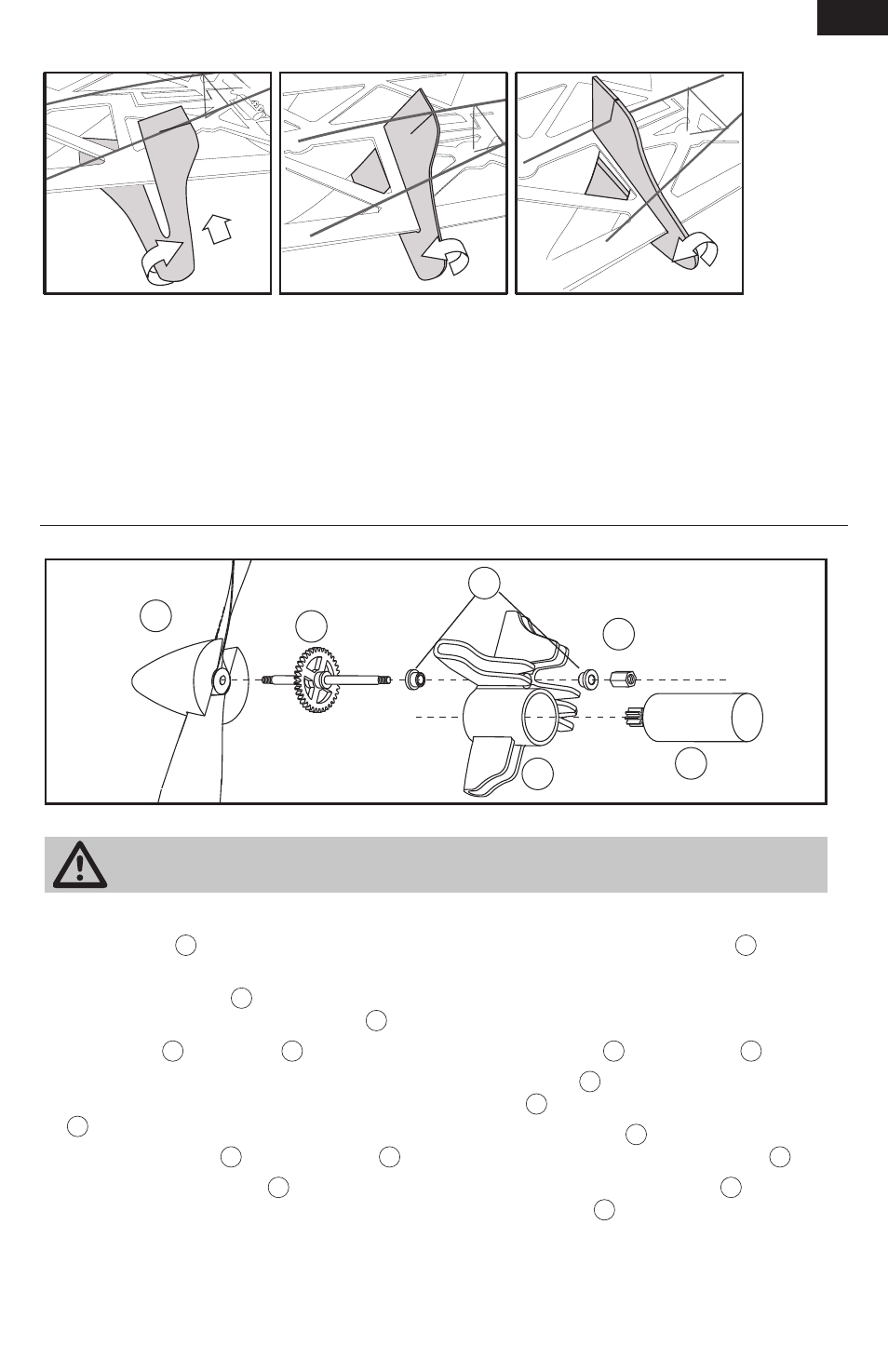
1. Turn SFG so it is near flat in relation to the wing.
2. Lower part of SFG with pre-cut slot must go
under carbon wing supports.
3. Put channel in SFG on wing.
4. Turn SFG carefully so rear support goes in slot in
SFG (see illustration).
5. Attach SFG to wing and carbon supports using
foam-safe CA.
6. Attach an SFG on other wing using instructions
above.
Installation of Side Force Generator (SFG)
B
D
F
A
E
C
Note: Wiring not shown