Control centering factory control horn settings, Control direction test – E-flite UMX Habu 180 DF BNF Basic with AS3X Technology User Manual
Page 7
7
EN
Before the fi rst fl ights, or in the event of an
accident, make sure the fl ight control surfaces
are centered. Adjust the linkages mechanically if
the control surfaces are not centered. Use of the
transmitter sub-trims may not correctly center the
aircraft control surfaces due to the mechanical
limits of linear servos.
1. Make sure the control surfaces are neutral
when the transmitter controls and trims are
centered. The transmitter sub-trim must
always be set to zero.
2. When needed, use a pair of pliers to carefully
bend the metal linkage (see illustration).
3. Make the U-shape narrower to make the
connector shorter. Make the U-shape wider
to make the linkage longer.
Centering Controls After First Flights
For best performance with AS3X, it is important
that excessive trim is not used. If the aircraft re-
quires excessive transmitter trim (4 or more clicks
of trim per channel), return the transmitter trim
to zero and adjust the linkages mechanically so
that the control surfaces are in the fl ight trimmed
position.
Control Centering
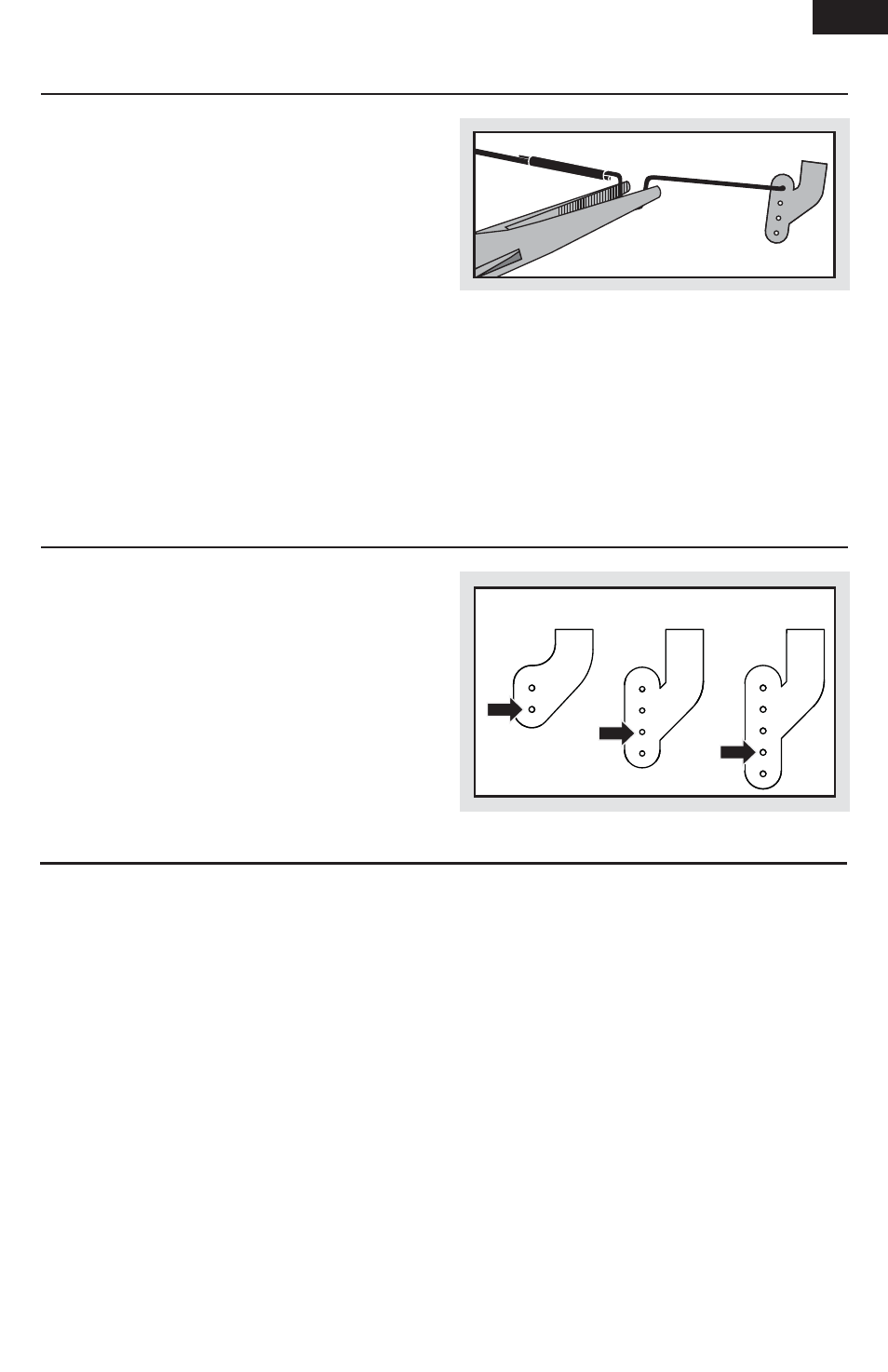
Factory Control Horn Settings
The illustration shows linkage positions chosen for
the most balanced aerobatic response. Linkage
connections on the control horns directly affect
aircraft response.
Aileron Elevator Rudder
Control Direction Test
You should bind your aircraft and transmitter
before doing these tests. Move the controls on
the transmitter to make sure the aircraft control
surfaces move correctly and in the proper direction.
Make sure the tail linkages move freely and that
paint or decals are not adhered to them.