Channel functions and options, Positioning the projector, Dmx 512 – Clay Paky MINISCAN (HTI 150) User Manual
Page 2
8
TEST
256
128
64
32
16
8
4
2
1
ON
10
9
8
7
6
5
4
3
2
1
11 12
PA
N
TIL
T
TILT
GOBO
PAN
COL
Is
THE DIGITAL START
ADDRESS IS THE SUM
OF THE NUMBERS
PRODUCED BY THE
SELECTED SWITCHES
DIGITAL
START
ADDRESS
AND
OPTIONS
SELECT
EG.
RESPOND
C.1 - 4
EG.
RESPOND
C.17 - 20
RUN TEST
SEQUENCE
DMX 512
RS232/423
: 1 = ,2 = SIG - ,3 = SIG +
: 1 = ,2 = SIG ,3 = SIG
DIGITAL INPUT
ANALOGUE
INPUTS 0 - 10V
Projector
1-4
5-8
ON
OFF
ON
OFF
TEST
256
128
64
32
16
8
4
2
1
OFF
ON
OFF
ON
OFF
ON
OFF
ON
OFF
ON
OFF
ON
OFF
ON
OFF
ON
OFF
ON
1
2
3
9-12
4
13-16
5
17-20
6
21-24
7
25-28
8
29-32
9
33-36
10
37-40
CODE
- Channels
Projector
- Channels
Projector
- Channels
Projector
- Channels
Projector
- Channels
Projector
- Channels
Projector
- Channels
Projector
- Channels
Projector
- Channels
Projector
- Channels
• Aligning the beam
Having completed all the operations
indicated thus far, loosen the knobs
(3), manoeuvre the projector on
the bracket (2) until the beam is
directed at centre stage, then
retighten the knobs (3).
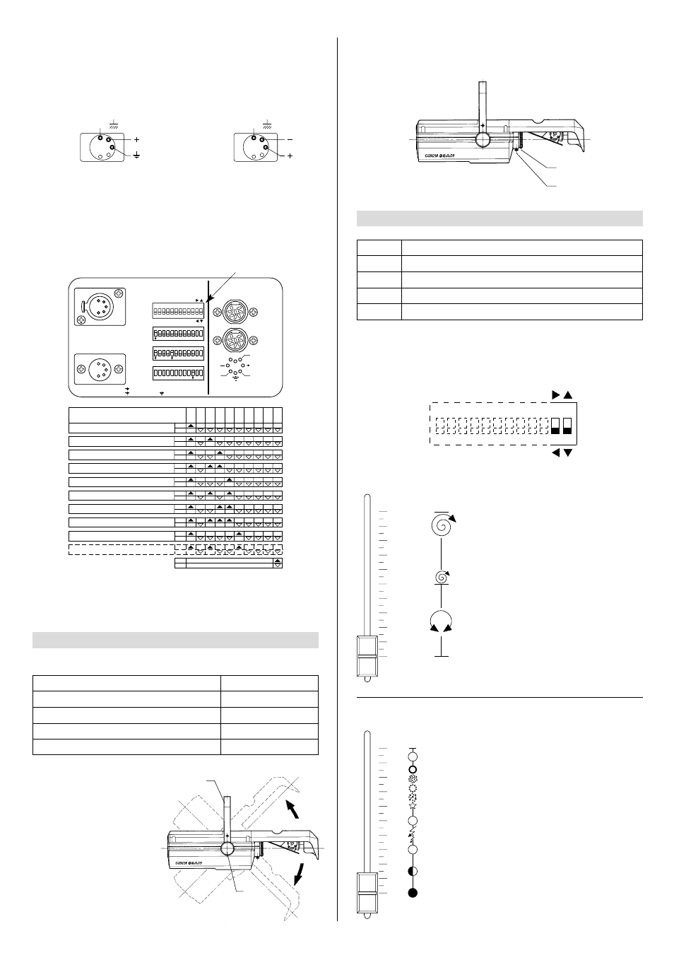
• Projector address codes (for digital signals)
A single MINISCAN utilizes 4 control channels. To ensure that the different projec-
tors are addressed correctly by the controller, a code must be assigned to each one.
The operation is carried out on each MINISCAN by setting the dip-switches as
indicated in the table below.
Before positioning the projector, set the channels as shown in the following table:
• Adjusting the lens
Move the lens (6) back and forward until the projected image is satisfactorily focused,
then tighten the knob (7).
Projector selection
CHANNEL FUNCTIONS AND OPTIONS
4
Select the options by setting the dip-switches as indicated.
POSITIONING THE PROJECTOR
3
CHANNEL
1 COLOUR WHEEL
2 GOBO CHANGE/DIMMER/STOPPER/STROBE
3 PAN
4 TILT
POSITION OF SLIDER
0% (white beam)
100% (white beam)
50% (Central position)
50% (Central position)
CHANNEL
1
2
3
4
FUNCTION
COLOUR WHEEL
GOBO CHANGE/DIMMER/STOPPER/STROBE
PAN
TILT
TEST
256
128
64
32
16
8
4
2
1
ON
10
9
8
7
6
5
4
3
2
1
11 12
PA
N
TIL
T
OPTIONS
To connect a DMX line, a terminating plug (7) with a 100
Ω
resistor wired between pins
2 and 3 must be fitted to the last projector connected in series; the plug is not required
when using a RS232/423(PMX) signal.
The wires must not come into contact with each other or with the metal cas-
ing of the plug.
The casing of the plug/socket must be connected to the screen and to pin 1 of
the connectors.
Having completed the operations described above, press the on/off switch (5). Check
that the warning light comes on and that the auto-reset sequence starts.
SIGNAL
SCREEN
SIGNAL
5
4
3
2
1
DMX
512
SIGNAL
SCREEN
SIGNAL
RS232/423
(PMX)
1
2
3
4
5
2
3
6
7
In the 0% to 50% range of adjustment, the
change of colour in response to the move-
ment of the potentiometer is linear and
continuous, so that the slider can be
stopped in intermediate positions to obtain
a two colour beam.
From 50% to 100% the wheel rotates con-
tinuously with speed increasing steadily
from 0 to 300 rpm.
• COLOUR WHEEL - channel 1
0
1
2
3
4
5
6
7
8
9
10
PINK
BLUE
ORANGE
GREEN
VIOLET
YELLOW
RED
WHITE
In the 0% to 30% range of adjustment, the
dimmer opens gradually to maximum aper-
ture.
Strobe effect is produced from 30% to
49.7%, with frequency increasing from 1 to
7 flashes per second.
At 50% the aperture is fixed.
The gobo sequence is produced between
60% and 85% of the slider travel, as indi-
cated in the diagram.
The aperture remains fixed between 85%
and 100% of the range.
• GOBO ROTATION /OSCURATORE/STOP/STROBO - channel 2
0
1
2
3
4
5
6
7
8
9
10
Setting the TEST switch to the ON position for a few seconds with the projector pow-
ered-up, an auto-reset routine is carried out. Leaving the TEST switch at the ON posi-
tion for a longer period, a full self-test program will be completed; once the operation
has terminated, return the switch to the OFF position.