English, Lens units, Maintenance – Clay Paky COMBICOLOR (575) User Manual
Page 3
7
250 V
5A T
5 x 20
FUSE
LENS UNITS
5
Objective lens 1:2,2/100 - Standard equipment
Objective lens 1:1,9/190 - Available on request
Objective lens 1:3,3/300 - Available on request
0
1
2
3
4
5
6
7
7
6
5
4
3
2
1
10,3
°
BEAM OPENING m
762
190
84,6
47,7
30,5
21,2
15,5
11,9
353
88,3
39,2
22,1
14,1
9,85
7,25
5,48
254
63,5
28,2
15,9
10,1
7,06
5,2
3,9
2.736
684
304
171
109
76
56
42
3.800
950
422
238
152
106
78
59
8.200
2.050
911
513
328
228
167
128
HMI 575W (lux)
HMI 575W (fc)
HTI 300W (lux)
HTI 300W (fc)
HMD 300W(lux)
HMD 300W(fc)
0
1
2
3
4
5
6
7
7
6
5
4
3
2
1
6
°
BEAM OPENING m
1.003
251
111
62,7
40,1
27,9
20,4
17,6
722
181
80,3
45,1
28,9
20,1
14,7
12,6
511
227
2.044
128
81,8
56,8
41,7
32
7.776
1.944
864
486
311
216
158
136
10.800 2.700
1.200
675
432
300
220
189
5.500
2.444
22.000
1375
880
611
449
344
HMI 575W (lux)
HMI 575W (fc)
HTI 300W (lux)
HTI 300W (fc)
HMD 300W(lux)
HMD 300W(fc)
20
°
0
1
2
3
4
5
6
7
7
6
5
4
3
2
1
BEAM OPENING m
74,9
18,8
8,27
4,65
2,97
2,04
1,58
1,21
104
26
11,5
6,5
4,18
2,88
2,14
1,67
216
53,9
24
13,5
8,64
5,95
4,37
3,34
806
202
89
50
32
22
17
13
1.120
280
124
70
45
31
23
18
2.320
580
258
145
93
64
47
36
HMI 575W (lux)
HMI 575W (fc)
HTI 300W (lux)
HTI 300W (fc)
HMD 300W (lux)
HMD 300W (fc)
16’ 5”
DISTANCE ft in
32’ 10” 49’ 3”
65’ 7”
82’
98’ 5” 114’ 10” 131’ 3”
0”
5
10
15
20
25
30
35
40
DISTANCE m
0
1,76
3,52
5,28
7,04
8,80
10,56
12,32 14,08 DIAMETER m
0
5’ 9”
DIAMETER ft in
11’ 7”
17’ 4”
23’ 1” 28’ 10” 34’ 8”
40’ 5” 46’ 2”
0”
5
10
15
20
25
30
35
40
DISTANCE m
0
16’ 5”
DISTANCE ft in
32’ 10” 49’ 3”
65’ 7”
82’
98’ 5”
114’ 131’ 3”
0”
0,9
1,8
2,7
3,6
4,5
5,4
6,3
7,2
DIAMETER m
0
2’ 11”
DIAMETER ft in
5’ 11”
8’ 10” 11’ 10” 14’ 9”
17’ 9”
20’ 8” 23’ 7”
0”
5
10
15
20
25
30
35
40
DISTANCE m
0
16’ 5”
DISTANCE ft in
32’ 10” 49’ 3”
65’ 7”
82’
98’ 5”
114’ 131’ 3”
0”
0,52
1,04
1,56
2,08
2,6
3,12
3,64
4,16
DIAMETER m
0
1’ 8”
DIAMETER ft in
3’ 5”
5’ 1”
6’ 10”
8’ 6”
10’ 3” 11’ 11” 13’ 8”
0”
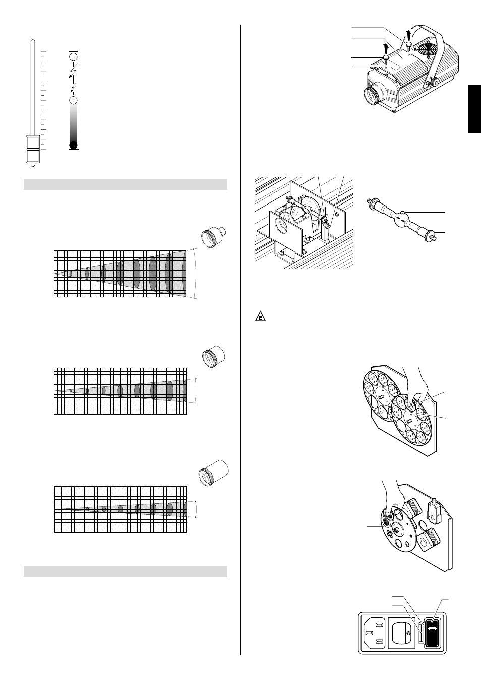
MAINTENANCE
• Changing colour filters
Having opened the projector, iden-
tify the filter to be changed, grip
firmly between thumb and forefin-
ger and push against the spring
clip (15) until free of the fixed clips
(16). Bend the filter outwards and
remove. Offer the new filter to the
spring clip (15) and anchor behind
the fixed clips (16).
• Changing metal gobos
Having opened the projector, iden-
tify the gobo to be replaced and
push gently toward the clips (17)
until free.
Offer the new gobo to the first two
clips, push gently and locate
behind the remaining clips,
checking for flatness.
• Changing fuses
To change the fuses, press the tab
(18) and pull out the fuse holder
(19). Replace any blown fuse with
one of the same type and rating as
indicated on the label (20) atta-
ched to the holder (19). Insert the
fuse holder and push in to engage
the tab (18).
6
IMPORTANT: isolate the projector from the electrical power supply before commen-
cing maintenance work of any description.
The maximum temperature on the outer surface of the projector under normal ope-
rating conditions is indicated on the lamp change label (1).
After switching off, do not remove any part of the projector for at least 10 minutes, as
indicated on the lamp change label (1). Once this time has elapsed, the risk of a lamp
exploding is practically zero. If the lamp needs changing, wait a further 15 minutes to
avoid the risk of burns. In the event of a lamp exploding, the appliance is designed
to prevent fragments of glass from being scattered.
Lenses and clear filters supplied with the appliance must be fitted at all times, and if
visibly damaged must be replaced promptly with genuine spares.
In the 0% to 50% range of adjustment,
the dimmer opens gradually to maximum
aperture.
Strobe effect is produced from 55% to
95%, with frequency increasing from 1 to
11 flashes per second.
The aperture remains fixed between 95%
and 100% of the range.
• DIMMER/STOPPER-STROBE - channel 4
0
1
2
3
4
5
6
7
8
9
10
GRAPHS SHOWING BEAM DATA AND ILLUMINATION VALUES
• Opening the projector
Free the access cover (11) by
loosening the knobs (10), and
remove from the projector.
Once the necessary work has
been completed, refit the cover
(11) and retighten the knobs (10).
• Changing the lamp
Open the projector, loosen the two side nuts (12) of the lamp to be changed and
remove it from the supports (13).
Remove the new lamp from its packaging, loosen the two side nuts (12) and
locate the lamp in the supports (13). Finally, retighten the nuts.
1
14
16
15
12
10
11
10
IMPORTANT: for uniform distribution of the light beam, the lamp must be positioned
so that the glass pip (14), on the bulb does not coincide with the optical axis of the
projector. With this in mind, locate the pip as high up as possible.
CAUTION: The projector uses a high pressure discharge lamp with
external starter.
- When fitting a new lamp, read the manufacturer’s instructions carefully.
- The lamp must always be changed without delay if damaged or deformed
by heat.
ENGLISH
17
20
19
18
12
13