Maintenance, Code – Clay Paky ASTROSCAN (HMI 1200) User Manual
Page 4
10
MAINTENANCE
4
• Opening and closing the cover
Loosen the knob (34) and remove the re-lamping cover (18).
After maintenance refit the cover (18) and lock the knob (34).
34
18
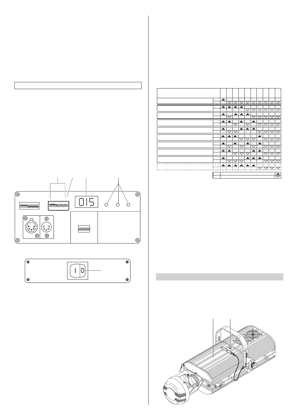
• Projector coding
Each ASTROSCAN requires 9 or 14 control channels. For these to be correctly
addressed to each projector it is necessary to code the projectors. This operation
needs to be carried out on each ASTROSCAN by switching the microswitches (32)
according to the table below.
Codes can be assigned with the projector off, although the operation will be easier
with the projector on, as the decade address corresponding to the binary code set
with the microswitches is shown on the 3-digit display (30).
When the information of "Total hours", "Bulb hours”, “Bulb strikes” and “Address" is
scrolling on the display and you use the DIL switches of the addresses (32), the
display will instantly show the new address selected. After a few seconds the above
information will start scrolling again if at least one of the above conditions remains.
On turning the TEST microswitch (33) onto ON the projector runs a self-check,
during which the effects are mechanically reset with the projector on. At the end of
the operation, or whenever you want to interrupt this procedure, turn the TEST
microswitch back onto OFF.
When sending 0% levels to all channels, the unit will start an automatic re-calibration
after 2 seconds. This operation will reposition any effects to their correct settings.
The entire re-calibration cycle lasts approximately 35 seconds and can be stopped
at any time by simply setting a channel at a level above 0. It is recommended not to
interrupt re-calibration, but to let it end regularly, once 10 seconds have elapsed
from its start.
Projector
1 - Channels 1-14
1
2
4
8
16
32
64
128
256
TEST
OFF
ON
CODE
Projector
2 - Channels
15-28
OFF
ON
Projector
3 - Channels
29-42
ON
OFF
Projector
4 - Channels
43-56
ON
OFF
Projector
5 - Channels 57-70
ON
OFF
Projector
7 - Channels 85-98
ON
OFF
Projector
8 - Channels
99-112
ON
OFF
Projector
9 - Channels
113-126
ON
OFF
Projector
10 - Channels
127-140
ON
OFF
OFF
ON
Projector
6 - Channels
71-84
ON
OFF
• Switching on the projector
After carrying out all the above operations, press the switch (29) checking it all
works properly.
At switch on, the software contained in the DMX Receiver microprocessor does a
checksum (automatic check) while the three figure display (30) is off and the three
LEDs (31) controlling the input signal are all on. After a few seconds, the projector
starts the mechanical zero setting of the effects. Only at the end of this procedure
it switches on (option 3 OFF), or you can switch on (option 3 ON) the lamp. At the
same time, if the checksum has had a positive result, a code corresponding to the
version of the DMX Receiver microprocessor (installed) appears on the display.
This code is displayed for about 5 seconds, then only one of the three LEDs
relating to the connected input signal stays on, while the following information
scrolls on the display once:
DIGITAL START ADDRESS SELECT
OPTION SELECT
DIGITAL INPUT LEDS
1
16
1
2
4
8
16
128
32
64
TEST
256
ON
1 2
4
3
6
5
7 8
10
9
DIGITAL INPUT
1 2
4
3
6
5
The above information can also be displayed by carrying out at least one of the
following operations:
• Setting all the DIL (Dual-In-Line) switches of the addresses (32) onto zero.
• Activating the TEST procedure, turning the specific DIL switch (33) ON.
• Setting the projector on blackout (20 channels starting from the selected starting
address, all at level zero).
About two minutes after the projector has been switched on, the luminous intensity
of the display (30) decreases to 1/32 of the maximum value. The maximum
luminosity is restored automatically if you use the microswitches to select the
DMX address, set the options or activate the TEST function. Approximately two
minutes after the last operation listed above has ended, the luminosity of the display
decreases again.
32
33
30
29
31
in which “Total hours” is the total number of hours of the fitting’s life, “Bulb hours” is
the number of hours of the lamp’s life, “Bulb strikes” is the number of times the lamp
has been switched on and “Address” is the selected starting address for the
projector control signals.
After the information has scrolled, the projector address will stay displayed.
Total hours - XXX Bulb hours - XXX Bulb strikes - XXX Address - XXX