Possible configurations, Operation, tips & tricks, Specifications – Blizzard Lighting wiCICLE Wireless DMX System (Rev B) User Manual
Page 2
POSSIBLE CONFIGURATIONS
The diagrams below show possible confi gurations. Multiple receivers may
be used in any possible confi guration.
OPTION 1. A transmitter (MALE XLR CONNECTOR) is connected to the
output of the controller, and a receiver (FEMALE XLR CONNECTOR) is con-
nected at the input of the fi rst DMX fi xture.
OPTION 2. A transmitter (MALE XLR CONNECTOR) is connected to the
output of a DMX fi xture, and a receiver (FEMALE XLR CONNECTOR) is con-
nected to the input of the next DMX fi xture.
OPERATION, TIPS & TRICKS
Each wiCICLE acts as both a transmitter and a receiver, depending on whether a DMX
source is applied to the integral XLR connector. This is an extremely powerful feature
of the system, however, it also requires 1 piece of due dilligence, and that is the re-
moval of extraneous DMX signals from your lighting rig BEFORE proceeding.
SO: BEFORE DOING ANYTHING ELSE, YOU SHOULD DISABLE ANY BUILT-IN
PROGRAMS IN THE FIXTURES YOU WISH TO CONNECT AND/OR SET THEM AS
SLAVES PRIOR TO RETURNING THEM TO DMX MODE (IF APPLICABLE). Most
fi xtures contain a built-in automatic, sound active or custom program which
is designed to operate with the fi xture NOT connected to a DMX chain.
Some of these programs will automatically run unless the fi xture is set to slave mode.
These fi xtures typically sense DMX automatically and switch to DMX mode upon re-
ceiving DMX signal (our Pucks do that!)
If you plug a wiCICLE “receiver” into an autosensing fi xture set as a “master, “chances
are good that the wiCICLE “receiver” will begin transmitting the master program. Most
times, this is undesirable, and taking the two seconds to switch these programs off will
solve a lot of ails.
Got that done? Good! Then let’s proceed!
1. Power on the wiCICLE™ Transmitter and Receiver.
2. Press the button on the Transmitter to select the operating channel group. (The
system will store this setting for future use)
The 7-Color Status LED will change color to indicate the current channel group:
· GROUP 1:
RED
· GROUP 2:
GREEN
· GROUP 3:
YELLOW
· GROUP 4:
BLUE
· GROUP 5:
VIOLET
· GROUP 6:
CYAN
· GROUP 7: WHITE
3. Follow the same procedure on the Receiver to select the channel group.
4. Once both the transmitter and receiver(s) are both set to the same channel group,
connect the transmitter to the DMX controller or the DMX out of a fi xture on your
DMX chain. Connect the receiver to the fi xture you wish to control.
5. Once a DMX signal is provided to the transmitter, the status LED will blink
RED
slowly until communication is established with the receiver. The status LED on the
receiver(s) will fl ash
GREEN
slowly until communication is established.
6. Once the clearest channel is auto-selected, the status LEDs will blink quickly.
7. That’s It!
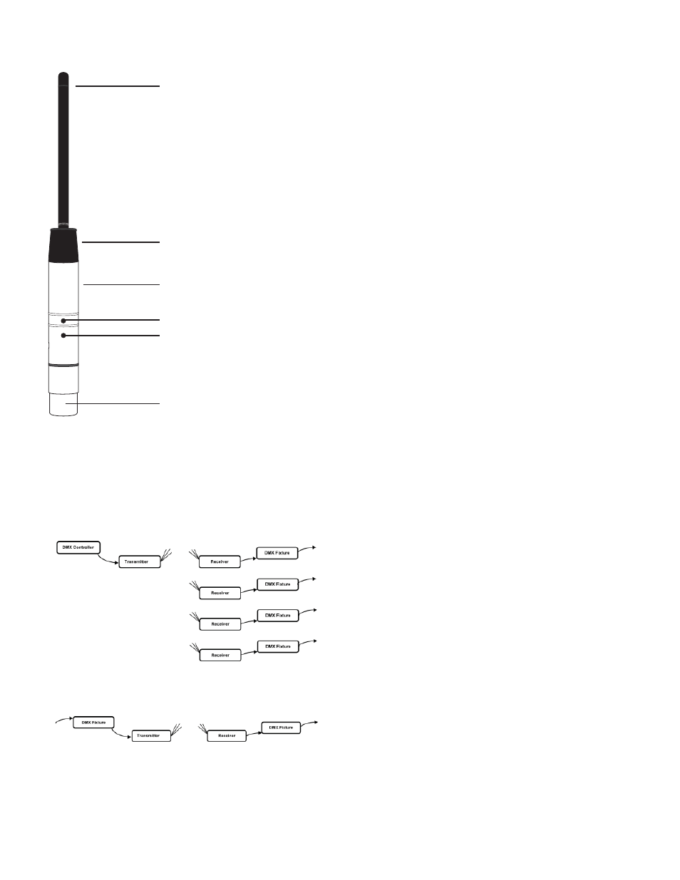
WE HAD THIS PAGE, SO WE FIGURED WE’D DRAW
YOU A PICTURE:
Antenna Housing & 1/2-wave
Antenna
Antenna ferrule & articulation
joint
Stainless Steel Housing
Recessed Selector Button
Status LED
3-Pin XLR Connector
(Male on transmitter, Female
on receiver model)
NOTE: “GROUP” number
also corresponds to the
“GROUP” setting on our
LightCaster™ wireless DMX
Transceiver.
SPECIFICATIONS
Model:
wiCICLE™
Voltage:
5VDC, 1000ma
Supplied by 100~240V, 50/60Hz
AC Adaptor or directly by
wiCICLE ENABLED Fixtures and Equipment
Operating Band:
2.4Ghz ISM
Max Operating Range:
300 Meters (Line of Sight)
Max Transmission Power: 20dBm
Receiver Sensitivity:
-94dBm
Data Input (Transmitter): 3-Pin Locking XLR Male
Data Ouput (Receiver):
3-Pin Locking XLR Female
Protocol:
USITT DMX-512
Dimensions:
8.5”(L) x 0.75” (Diameter)
215mm
x
19mm
Weight:
.1 Lbs. / .05 kgs.
Duty Cycle:
None
Working Position:
Any Safe, Secure Position
Warranty: 2
Years
Specifi cations and improvements in the design of this unit and this manual are subject
to change without any prior written notice.