BEA Multibeam User Manual
Page 2
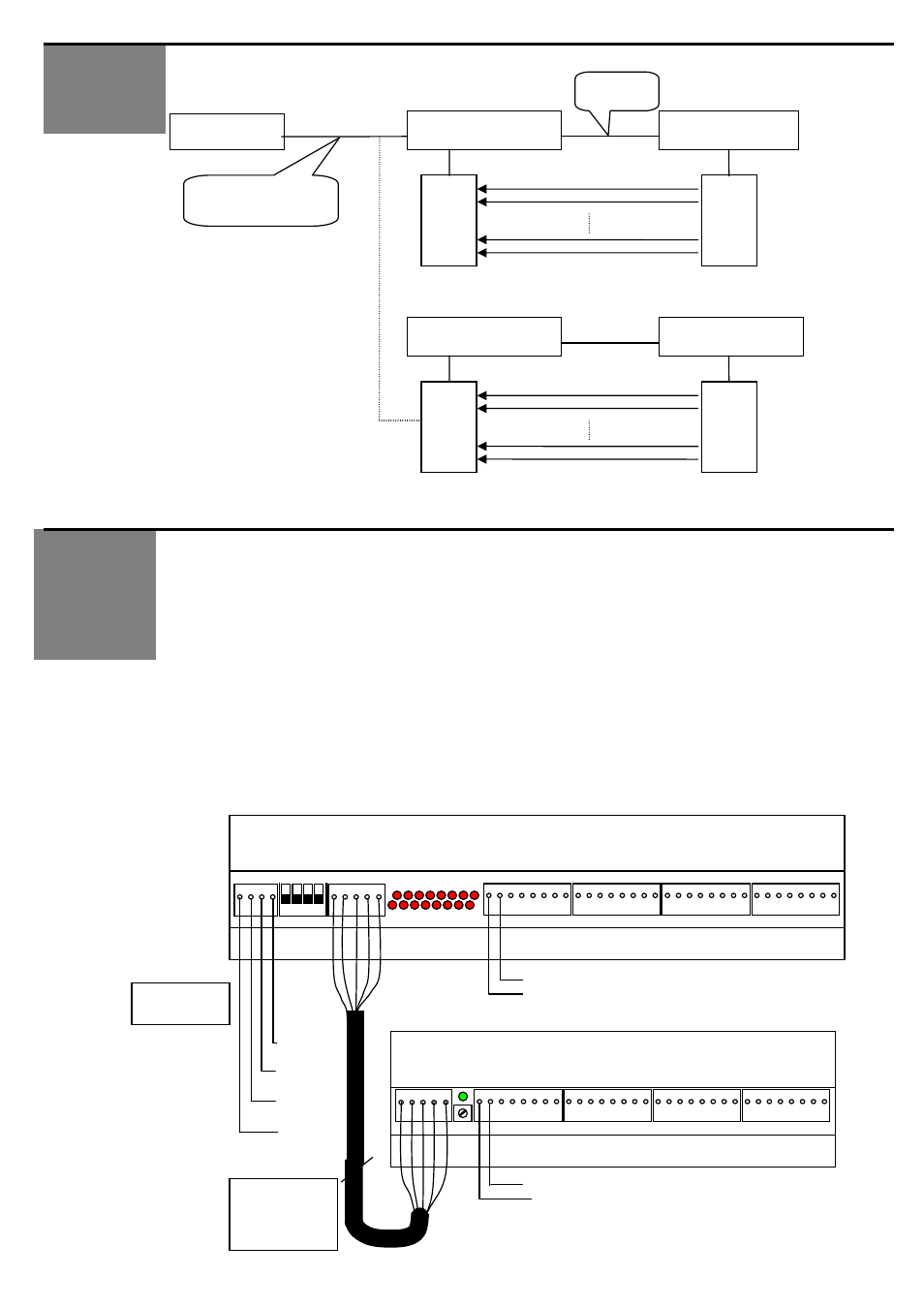
Functional wiring structure:
On the receiving module 16 red LEDs show the status of each beam. Plug connectors with 3.5 mm
pitch are used. The 2 twisted wires enable the connection of each head to the controller. The wires
must be between 0.5 m and 5 m long. Thanks to the multiplexing of the heads, there is no interference
between two heads.
The status information of the beams are transmitted to the controller via a RS485 communication. It is
possible to connect other terminals (maximum 32) on this bus.
The 2 modules composing the system are housed in aluminum profiles that can be fixed with screws or
with double-side adhesive.
A green LED on the
emitting module indicates if the module is on. If the link between the 2 modules is
not correct, the LED will remain off and the MULTIBEAM will not work properly.
A potentiometer on the emitting module allows to adjust them emission power in order to reduce the
influence of one module to an other module in close proximity (turn clockwise = increase emission
power).
The receiver has a green cable and the emitter a yellow cable.
Wiring Diagram:
WIRING AND
INSTALLATION
FUNCTIONNAL
DESCRIPTION
16 times
Address 1
Controller
Receiving module
Emitting module
5 wires
Communication
and supply
Receivers
Emitters
Address 2
16 times
Receiving module
Emitting module
Receivers
Emitters
P2 Potentiometer 16 emitter head conectors
Status LED
+24V
RS485+
RS485-
GND
1-- - 5
1-- -- 5
P1 SW1 P2 LEDS 16 Receiver head connectors
receiving and communication module
Emitting module
5 wires cable
between the 2
modules
Lmax = 5m
GND
IN
First receiver head wiring
OUT
First emitter head wiring
GND
4 wires cable
to controller