Installation instructions, Warning, Sub-frame hitch – Briggs & Stratton 1695195 User Manual
Page 4: Initial assembly
4
Installation Instructions
Sub-Frame Hitch
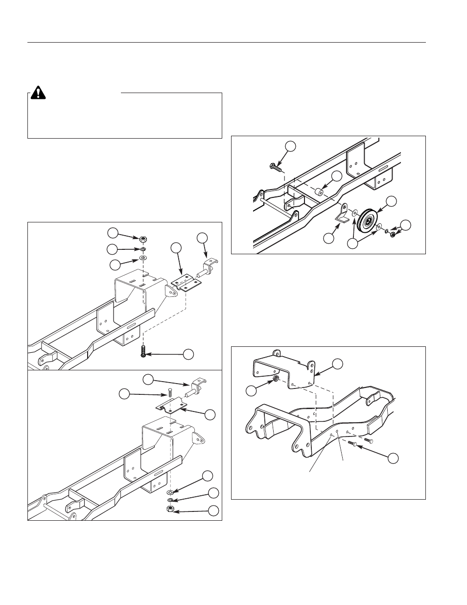
Figure 2. Install Support Clamp
A. 5/16-18 x 1 Carriage Bolt
D. 11/32 Washer
B. Hook Assembly
E. 5/16 Lockwasher
C. Support Clamp
F. 5/16-18 Nut
B
C
D
E
A
F
Figure 3. Front Pulley - Two-Stage Applications
A. Capscrew, 3/8-16 x 2-1/4
D. Washers, 3/8
B. Spacer, 3/8 x 1 x 1/2
E. Lockwasher & Nut
C. Belt Guide
F. Pulley
A
B
C
D
F
E
NOTE: Please read through these instructions and the
instructions of any other attachments before beginning
installation.
INITIAL ASSEMBLY
Assemble Hitch
1. Attach the support clamp (C, Figure 2) and hook
assembly (B) to the hitch. Secure with four 5/16-18 x
1 carriage bolts (A), washers (D), lockwashers (E),
and nuts (F). Do not tighten the hardware at this
time.
WARNING
Before beginning any service work turn off the
PTO, set the parking brake, turn off the ignition,
and disconnect the spark plug wire(s).
Conquest / 1700 /
2700 &
Prestige / 1800 /
2800 Series
B
C
D
E
A
F
Broadmoor /
1600 / 2600
Series
Change Pulley & Belt - Two-Stage Blower
Only
1. If using this hitch with a two-stage snowthrower, the
front idler pulley must be switched from the right hand
side of the hitch bracket, to the left, and an additional
3/8 x 1 x 1/2 spacer (B, Figure 3) and 3/8-16 x 2-1/4
capscrew (A) is required. Also install the 1703372
drive belt.
Assemble Push Bar Latch
1. Attach Push Bar Latch (B, Figure 4), to hitch. Secure
with four .31-16 x 1 bolts (A), and four .38-16 flange
nuts (C).
Two Wheel
Drive Models
Four Wheel
Drive Models
A
B
C
Figure 4. Assemble Push Bar Latch
A. Bolt, .38-16 x 1
C. Flange Nut, .38-16
B. Push Bar Latch