Ha b d w – B&D Mfg EA-QT User Manual
Page 4
Electrical: 1/60/230V
Insulation: Insulated Cabinet Approx. Volume of Fluid: 5 gal.
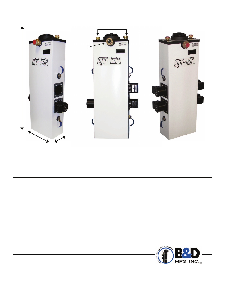
A = 1 1/4" Swivel B = 1 1/4" Union H = 43 1/2" W = 14"
D =21 1/2"
LETTER AFTER MODEL NUMBER FOR PUMP NEEDED: G= 2699-3 Speed(230V) M=26-116
CAUTION: For proper operation, water must be added as air is eliminated. The amount of water will be in proportion to
the amount of air eliminated.
3. After all air has been eliminated and full flow established, close valve No. 2 to place the system back into
full
operation.
SYSTEM READY
The complete system is now operational and ready for testing. Use the flow meter tool (Part 1-WFT40) which slips over
the inlet pipe inside the flow center. Read the actual flow rate being pumped through the flow center. By closing all the
loop valves but one pair, an actual flow rate can be read on the meter for each ground loop. This will indicate that all
loops are flowing properly. If any loop shows a significant reduction of flow an obstruction may be present in the loop.
Remove flow meter from the flow center canister and allow the pumps to run continuously for 24 hours. The flow center
will continue to eliminate any small air bubbles that remain in the system.
MODEL 1-1E-A-SS230QFC
Weight: 78 lb.
MODEL 2-1E-A-SS230QFC
Weight: 83 lb.
MODEL 2-2E-A-SS230QFC
Weight: 89 lb.
B&D Mfg, Inc
901 9th Street
Scranton, IA 51462
Phone (712) 652-3424
Fax (712) 652-3388
www.bdmfginc.com
Patent No. 5,244,037
©eg 2009-2013 B&D Mfg., Inc. all rights reserved.
4
08-2013
H
A
B
D
W