Audio Developments AD256 User Manual
Page 5
4
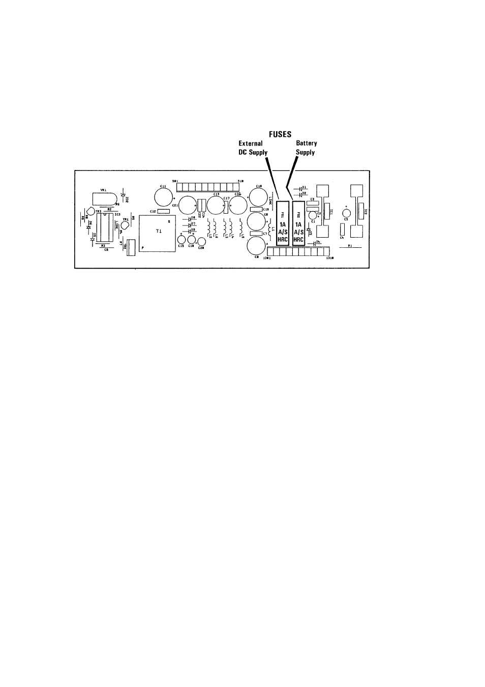
Fuses - to protect the mixer and internal power supply are mounted on the power
supply/converter board. Access is gained by removing the output module. 20mm, 1A
ANTI-SURGE HRC fuses are used - one for the internal battery power supply and one
for the external DC supply.
Output Limiter threshold - is set at the factory at +8dBu, but an internal preset
potentiometer allows adjustment to any other level above 0dBu. The limiters are to
be found on the output module printed circuit board.
Input Limiter threshold – is set at the factor at +10dBu, with the input and output
faders at their calibration points. An internal preset potentiometer allows adjustment to
any other level above 0dBu and is mounted on the main input printed circuit board.
Microphone powering - the mixer will remain unconditionally stable if the powering on
unterminated input channels is switched off - this also improves the noise
performance and crosstalk. Powering - 48V phantom or 12V tonader - may be
selected before or after the microphone is connected to the module.
Module fix screws - Hexagon head screws are used to fix the modules and back
cover. The size being 1.5mm HEX A/F with a 2.5M thread.
If it becomes necessary to remove modules or back cover it is strongly advised using
a good quality hexagonal head driver.
Use of a screwdriver, however desperate, is not recommended.
We wish you many trouble-free hours of use from your mixer. As a company, we are
fully committed to BS EN ISO 9001. Should you have any problems or require any
further information, please do not hesitate to contact us on:- tel 01922 457007 or by
fax on 01922 457008 or by e-mail [email protected].