Installation, Positioning and levelling, Electrical connection – Hotpoint Ariston C 3 VP6 R/HA User Manual
Page 2
2
GB
Before operating your new appliance please read
this instruction booklet carefully. It contains
important information concerning the safe installation
and operation of the appliance.
Please keep these operating instructions for future
reference. Make sure that the instructions are kept
with the appliance if it is sold, given away or moved.
The appliance must be installed by a qualified
professional according to the instructions provided.
Any necessary adjustment or maintenance must be
performed after the cooker has been disconnected
from the electricity supply.
Positioning and levelling
It is possible to install the appliance alongside
cupboards whose height does not exceed that of the
hob surface.
Make sure that the wall in contact with the beck of
the appliance is made from a non-flammable, heat-
resistant material (T 90°C).
To install the appliance correctly:
Place it in the kitchen, dining room or the bed-sit
(not in the bathroom).
If the top of the hob is higher than the cupboards,
the appliance must be installed at least 200 mm
away from them.
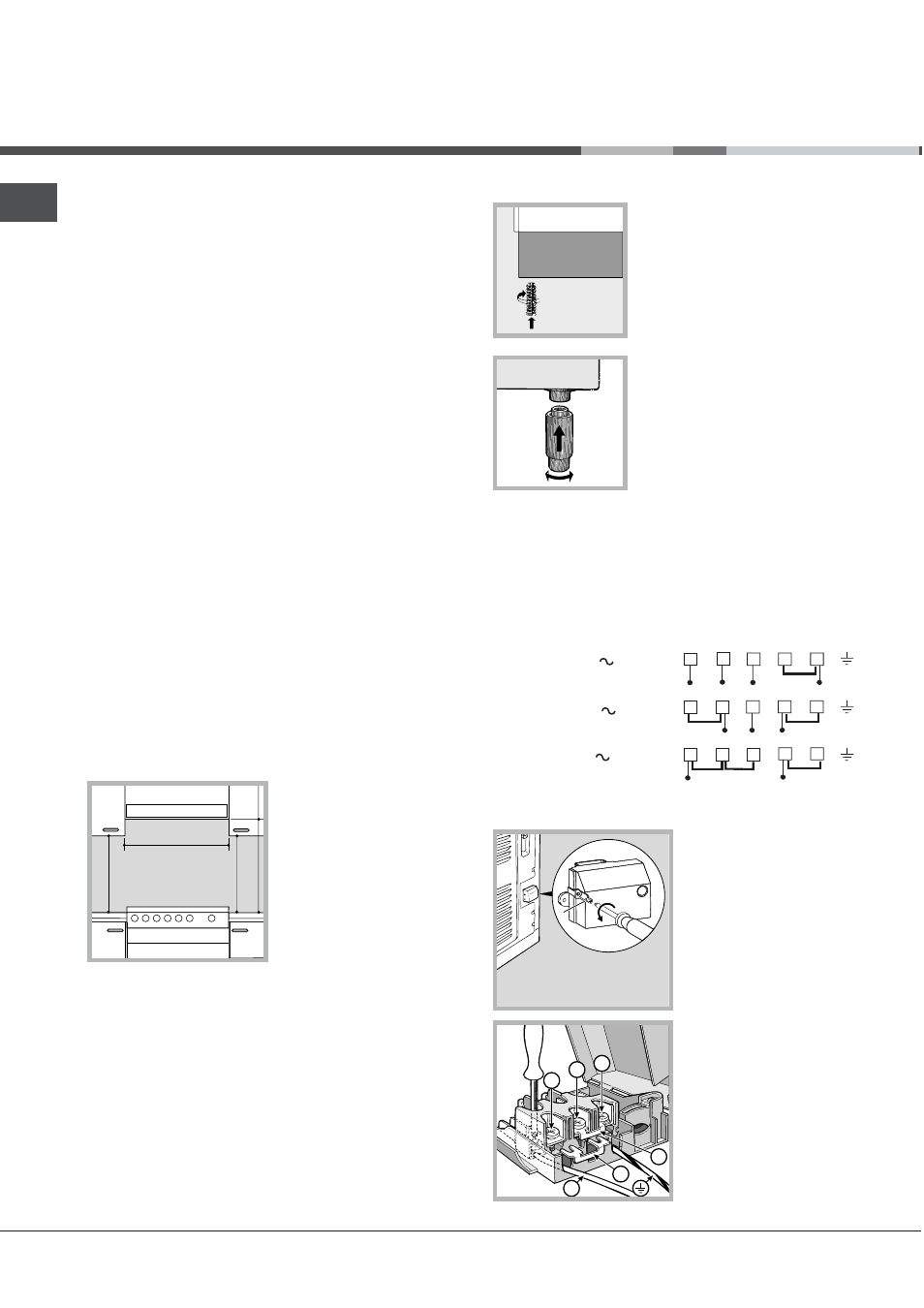
If the cooker is
installed underneath a
wall cabinet, there must
be a minimum distance
of 420 mm between this
cabinet and the top of
the hob.
This distance should be
increased to 700 mm if
the wall cabinets are
flammable (see figure).
Do not position blinds behind the cooker or less
than 200 mm away from its sides.
Any hoods must be installed according to the
instructions listed in the relevant operating manual.
Levelling
If it is necessary to level the
appliance, screw the
adjustable feet into the places
provided on each corner of the
base of the cooker (see
figure).
The legs* fit into the slots on
the underside of the base of
the cooker.
Electrical connection
Fitting the power supply cable
The cable should be suited to the type of electrical
connection used, according to the following
connection diagram:
1
2
3
4
5
1
2
3
4
5
1
2
3
4
5
R
S
T
N
R
S
N
R
N
400 3N
H05RR-F 5x2.5 CEI-UNEL 35363
400V 2N
H05RR-F 4x4 CEI-UNEL 35363
230V
H05RR-F 3x4 CEI-UNEL 35363
To install the power supply cable correctly:
1. Loosen the screw V
in the terminal board
and pull the cover to
open it (see figure).
2. Position the
connection supports A
(see figure) according
to the connection
diagram shown above.
The terminal board is
designed for single-
phase 230 V
connection: terminals 1,
2 and 3 are connected
Installation
HOOD
420
Min.
min.
650
mm. with hood
min.
700
mm. without hood
mm.
600
Min.
mm.
420
Min.
mm.
V
1
2
3
N
A
B
*
Only available in certain models.