Wood’s Powr-Grip FLEXR6HV11AIR User Manual
Page 10
Rev 0.0/1-12
8
FLEXR-HV11AIR: #35037:
T
O
C
HANGE THE
C
ONFIGURATION OF
V
ACUUM
P
ADS
The lifter can accommodate various load dimensions, depending on the position of the sliding
pad arms and movable pad mounts on the pad frame (see illustration in OPERATING FEATURES).
Move the pad arms and pad mounts inward or outward on the pad frame as needed to provide
adequate support across the load surface. The vacuum pads must be arranged symmetrically, to
keep the lifter balanced.
WARNING: Make sure all vacuum hoses are coiled or routed so they do not
become entangled, kinked or punctured.
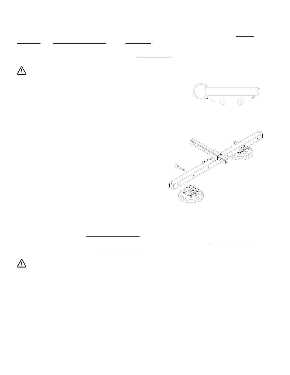
To position a pad arm, use the pull ring to remove the cotterless
hitch pin from the arm’s sliding mount. While making sure the
vacuum hose does not get pinched, slide the arm to the desired
position and align the holes for the pin. Push the pin through the
holes until the retaining ball emerges on the far side of the arm
mount. On the opposite end of the pad frame, position the
second sliding pad arm at an equal distance from the center of
the lifter.
To position each set of vacuum pads on a pad arm,
remove the cotterless hitch pins from the pad mounts,
move the pads inward or outward equal distances on the
pad arm, and secure them with the cotterless hitch pins.
Before applying the vacuum pads to a load, make sure
that all vacuum hoses are properly connected and will
not interfere with lifter operation.
T
O
A
PPLY THE
P
ADS TO A
L
OAD
Powering up the Lifter
Make sure the lever on the vacuum control valve is in the center position (see T
O
R
ELEASE THE
P
ADS FROM THE
L
OAD
: About Stand-By Mode to follow). Move the slide on the air supply valve to
the “ON” position, to engage the vacuum pump. The lifter is designed for the vacuum pump to
run continuously.
WARNING: Never place air supply valve in "OFF" position while operating lifter;
keep pump running throughout lift.
The supply valve must remain in the “ON” position while operating the lifter. Any interruption of
the vacuum flow during lifter operation could result in the release of the load and possible injury
to the operator (see T
O
L
IFT AND
M
OVE THE
L
OAD
: In Case of Power Failure to follow).
COTTERLESS HITCH PIN
1 PULL RING
2 RETAINING BALL