Assembly – Wood’s Powr-Grip MT5HV11DC User Manual
Page 6
Rev 7.0/12-12
4
MT5HV11DC: #35087
ASSEMBLY
1) Open the shipping container and remove all materials for restraining or protecting the vacuum
lifter. Save the container for use whenever the lifter is transported.
2) Suspend the lifter from a forklift or crane as follows: Select hoisting equipment rated to carry
the maximum load weight plus the lifter weight (see SPECIFICATIONS: Maximum Load
Capacity and Lifter Weight).
Note: Any application of the lifter and its remote vacuum package must conform to all
statutory or regulatory standards that relate to the hoisting equipment when used in its
geographical location (eg, OSHA Standard 1910.178 “Powered industrial trucks” for forklifts
used in the USA).
WARNING: Hoisting equipment hook must be fitted with restraining latch to
prevent lift spool from slipping off under any circumstances.
Raise the lift bar of the lifter to a vertical orientation and attach the hoisting equipment hook
to the lift spool.
Note: Some hoisting equipment hooks could interfere with an upright load that extends
beyond the lifter's pad frame. If the load would contact the hook during lifter operation, the
operator must prevent this by attaching a sling (or other rigging that does not interfere with
the load) between the hook and the lift spool.
WARNING: Any sling used must be rated to carry maximum load weight plus
lifter weight.
Use the hoisting equipment to raise the lifter out of the shipping container. Be careful to
avoid damaging any vacuum pads. Remove the pad covers and save them for use whenever
the lifter is stored.
3) Carefully remove the remote vacuum package from the shipping container, and connect the
electrical connectors uniting the battery to the battery charger and the vacuum generating
system.
2
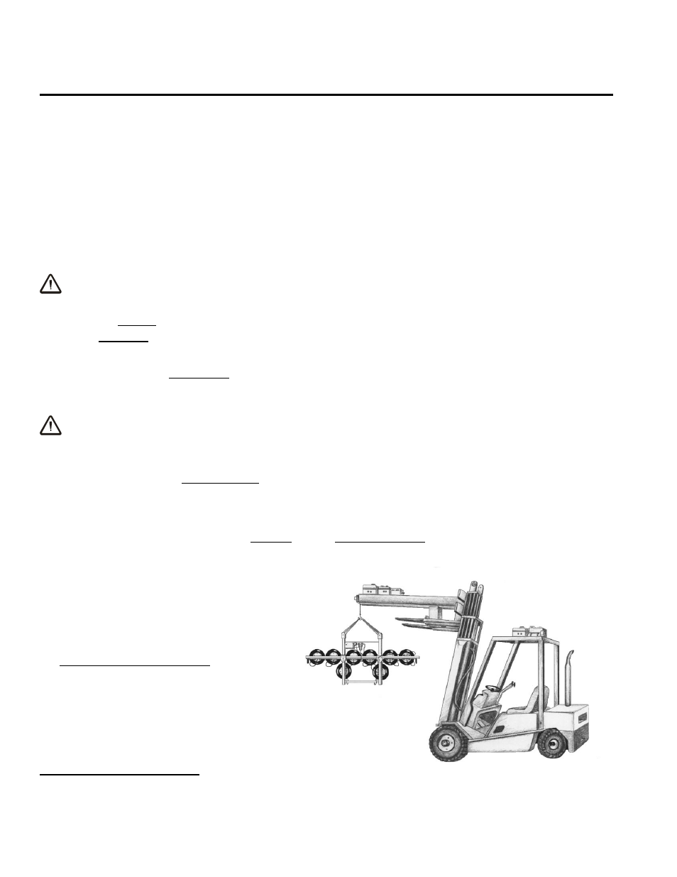
4) Attach the vacuum package securely
to the forklift or other hoisting
equipment in a protected location
where the vacuum package will
move with the lifter. Note that the
low vacuum warning light must
remain visible to the lifter operator
at all times (see OPERATION: T
O
L
IFT
AND
M
OVE THE
L
OAD
: Monitoring
Vacuum Indicators). The illustration
represents two potential mounting
locations. However, hoisting
2
If the operator disconnects the battery lead wires for any reason, s/he can consult the wiring diagram (provided) to reconnect
them.
location 1 -->
<-- location 2