Ift and, Ove the – Wood’s Powr-Grip MT49AC User Manual
Page 11
Rev 11.0/12-10
MANUAL TILTER • AC-VOLTAGE • 4-SCFM
#35084: 10
T
O
L
IFT AND
M
OVE THE
L
OAD
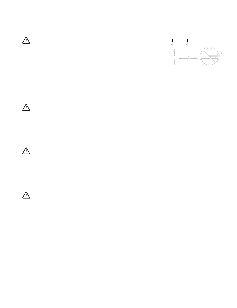
Positioning the Lift Bar
WARNING: Lift bar must be oriented vertically to lift
load.
Never lift the load from a flat position with the lift bar latched parallel
to the load. Always disengage the tilt latch (see T
O
T
ILT THE
L
OAD
to
follow) and raise the lift bar to a vertical orientation before attempting
to lift.
Load Capacity and the Lift Light
A lifter's Load Capacity is rated at a vacuum level of 16" Hg [-54 kPa] (see SPECIFICATIONS).
After the lifter has attained this level, the green vacuum lift light turns on to indicate that the
lifter is ready to lift the maximum load weight.
WARNING: Never attempt to lift load unless green light is illuminated.
Do not attempt to lift the load unless the lift light is illuminated; such an attempt could result in a
load release and possible injury to the operator.
Monitoring Vacuum Indicators
The vacuum lift light and the vacuum gauge must remain completely visible to the operator, so
that they can be monitored throughout the entire lift.
WARNING: Vacuum indicators must be visible to operator throughout entire lift.
The lifter’s vacuum pump runs continuously to maintain sufficient vacuum for lifting the
maximum load weight. If the vacuum system experiences leakage while the lifter is attached to
the load, the lift light turns off automatically, to signal the reduction in vacuum to the operator.
If the lift light turns off while you are lifting a load, make sure the vacuum gauge shows a
vacuum level of 16" Hg [-54 kPa] or higher. If not, move away and stay clear of the load until it
can be lowered to the ground or a stable support.
WARNING: Stay clear of any suspended load while vacuum level is lower than
16" Hg [-54 kPa].
Discontinue lifter use until the cause of the vacuum loss can be determined. If the lift light does
not turn on when the lifter is attached to clean, smooth, nonporous materials, the leakage is
likely to be in the vacuum system. In this event, perform the V
ACUUM
T
EST
(see MAINTENANCE)
and inspect the vacuum pads for damage (see MAINTENANCE: V
ACUUM
P
AD
M
AINTENANCE
:
Inspection). If the vacuum loss cannot be remedied immediately, perform inspection and
maintenance as needed to identify and correct any deficiency before resuming normal operation
of the lifter.
Controlling the Lifter and Load
When vacuum indicators show that the lifter is ready, use the hoisting equipment to raise the
lifter and load as needed to clear any obstacles in their path. Use the control handles to keep the
lifter and load in the desired orientation while they are suspended from the crane. Once
sufficient clearance is established, the load can be tilted as desired (see T
O
T
ILT THE
L
OAD
to
follow).