Wolo RC-100 WIRELESS WIZARD User Manual
Page 2
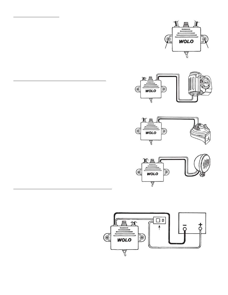
moUnTing receiVer: fig. 2
8. Locate the desired mounting location for the receiver, which should be in
close proximity to the horn, or the accessory that the Wireless Wizard will
control.
imporTanT: The receiver should always be mounted in a dry location.
If mounted in the engine compartment, make sure it is safe from engine
exhaust heat and moving parts.
9. Using the receiver’s base as a template; mark two hole locations and drill
to size, 1/8.
10. Mount and secure the receiver using the screws provided.
wiring receiVer To horn or accessorY: figs. 3 - 5
imporTanT: The Wizards POWER OUT wires are extended
from the back of the receiver case. Please note, the case has
been clearly marked above the wires:
•
power oUT To horn or accessorY– RED & BLACK
wires will be connected to device you want to turn on/off,
horn or accessory.
11.
red wire from wiZard’s power oUT porT:
Connects to the device’s (+) terminal or post (Fig 3).
imporTanT: some devices such as replacement horns
do not have polarity markings such as: (+) positive or (-)
negative. For such devices, the red wire can be connected to
either terminal (Fig.4 or Fig. 5).
12.
BLacK wire from power oUT porT: Connects to
the device’s (-) terminal or post (Fig.3).
imporTanT: some
devices such as replacement horns do not have polarity
markings such as: (+) positive or (-) negative. For such
devices, the black wire can be connected to either terminal
(Fig. 4 or Fig. 5).
wiring recieVer To 12-VoLT power soUrce: fig. 6
imporTanT: The Wizards POWER IN wires are extended from the back of the receiver case. Please note,
the case has been clearly marked above the wires. Always make sure that the power connection point can
handle the current load of the device being powered.
•
power in 12-VoLT – red &
BLacK wires will be connected to
12-volt power source, such as the
vehicle’s battery.
13.
BLacK wire from wiZard’s
power in porT: Connect to ground
by securing wire under any metal body
bolt or the negative (-) battery post.
Make sure that the METAL surface
around the bolt securing the wire is
clean of rust, oxidation and paint to make a good electrical connection.
14.
red wire from wiZard’s power in porT: Connect to positive (+) 12-volts such as the fuse block
or the positive (+) battery post. Always use the provided inline fuse.
imporTanT: The fuse should never
be more then ten (10) inches from the power source. Make sure the connection is at a location free from
corrosion or oxidation.
fig. 2
Drill
1/8”
Red
Red
+
–
Red
Red
Black
Black
Black
Black
Battery
Fuse
Holder
Drill
1/8”
fig. 3 – horn with polarity
fig. 4 – horn without polarity
fig. 5 – accessory without polarity
fig. 6