Installation, Venting introduction – Regency Bellavista B36XTE Medium Gas Fireplace User Manual
Page 17
Regency Bellavista™ B36XTE Gas Fireplace
17
INSTALLATION
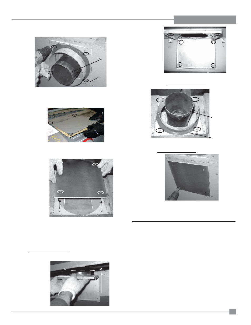
7) From the outside top of the fi rebox - remove the intake cover plate
by removing the 4 - 1/4" x 1/2 " screws. See Schéma 7.
6) From the outside top of the fi rebox - remove top insulation cover
plate and insulation fi lling - by removing 4 screws. See Schéma 6.
Discard cover plate and insulation fi lling.
5) From the outside rear of the fi rebox, remove the intake collar
assembly. Remove the 4 - 1/4" x 1/2" screws. See Schéma 5.
Schéma 5
Exhaust
Assembly
Intake Collar
Assembly
Schéma7
Schéma 6
Before proceeding to Step 8, inspect condition of all gaskets.
DO NOT install parts with damaged gaskets. Replace if necessary
with spare gaskets supplied.
8) From the inside of the fi rebox, place the exhaust assembly into
position as shown in Schéma 8 and secure with 8 - 1/4" x 1/2" screws
(Schéma 9). Ensure all screws are tight, but do not over tighten.
All 8 screws must be used.
Schéma 8
Schéma 9
10) From the outside rear of the fi rebox, install the intake cover plate
with 4 - 1/4" x 1/2" screws. Ensure all screws are tight, but do not
over tighten. All 4 screws must be used.
11) Set vent restrictor accordingly - see next page.
12) From inside the fi rebox, re-install the baffl e plate and heat
defl ector - reverse steps 2 & 3.
9) From the outside top of the fi rebox, install the intake collar assembly.
Secure with 4 - 1/4" x 1/2" screws. Ensure all screws are tight, but
do not over tighten. All 4 screws must be used.
Schéma 11
Intake Collar
Assembly
Exhaust
Assembly
Schéma 10
VENTING
INTRODUCTION
The B36XTE uses the "balanced fl ue" technology Co-Axial system.
The inner liner vents products of combustion to the outside while the
outer liner draws outside combustion air into the combustion chamber
thereby eliminating the need to use heated room air for combustion
and losing warm room air up the chimney.
Note: These
fl ue pipes must not be connected to any other
appliance.
The gas appliance and vent system must be vented directly to the
outside of the building, and never be attached to a chimney serving
a separate solid fuel or gas burning appliance. Each direct vent gas
appliance must use it's own separate vent system. Common vent
systems are prohibited.